
Oil, water and solid multi-phase separation method for natural gas

A multi-phase separation, natural gas oil technology, applied in separation methods, dispersed particle separation, chemical instruments and methods, etc., can solve the problems of shortened operating life of coalescing filter elements, difficult operation and management, inconvenient maintenance, etc., and achieve compact structure , less space required and strong applicability

Inactive Publication Date: 2010-06-09
XIAN TIANXIANG ENERGY TECH
View PDF0 Cites 15 Cited by
  • Summary
  • Abstract
  • Description
  • Claims
  • Application Information

AI Technical Summary

Problems solved by technology

The above-mentioned process is long, occupies a large area, and requires high investment (the PALL fine filter is imported), and it is inconvenient to maintain
Due to the limited removal of solid particles and water in natural gas by cyclone separation and double-tube gas-water separation in the process, a large amount of processing load is imposed on the PALL fine filter, which greatly shortens the operating life of the coalescing filter element of the PALL fine filter. about 3 to 4 months
There are things that need to be cleaned in each section of the equipment, which is difficult to operate and manage

Method used


Image

  • Oil, water and solid multi-phase separation method for natural gas
  • Oil, water and solid multi-phase separation method for natural gas
  • Oil, water and solid multi-phase separation method for natural gas

Examples


Embodiment Construction

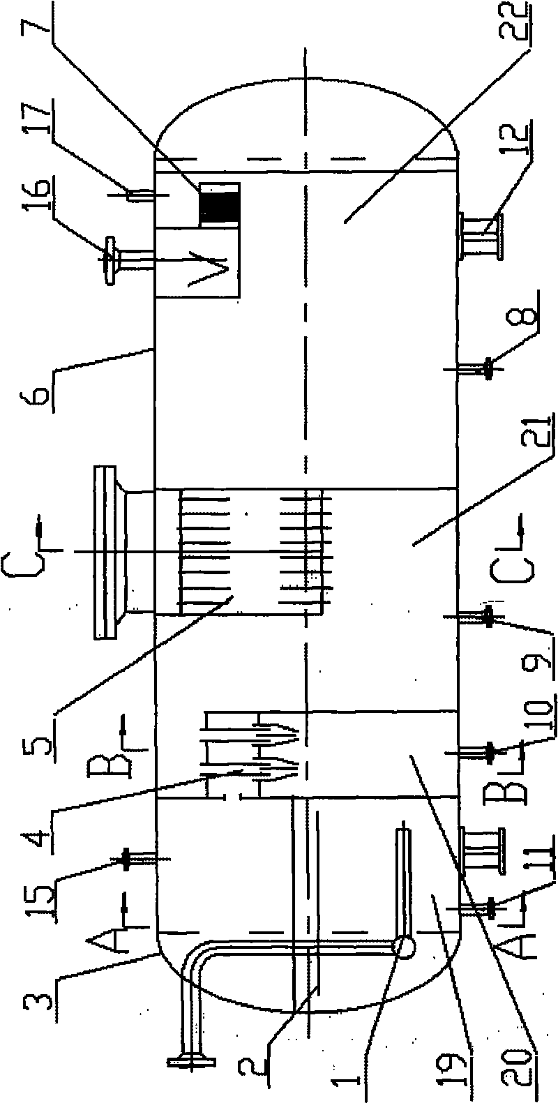
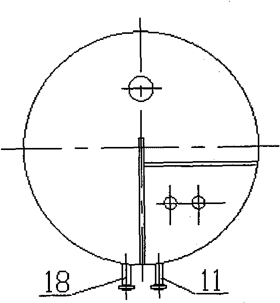
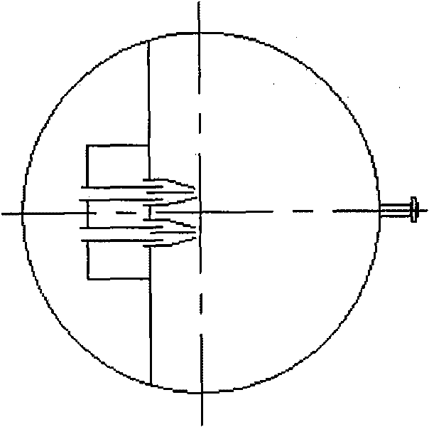
[0023] Such as figure 1 As shown, the equipment shell includes the left and right heads 3, the cylinder body 6 and the support 12. The left and right heads 3 seal and connect the left and right ends of the cylinder body 6 to form a horizontal tank structure. The horizontal tank body is divided into four areas, respectively It is the air intake water washing area 19, the cyclone separation area 20, the coalescence separation area 21, and the terminal mist trapping area 22. Through the four areas, the air intake → water washing → cyclone separation → oil and water coalescence → (gravity sedimentation) → Terminal mist capture → gas outlet (exported) natural gas oil, water, solid multi-phase separation process.

[0024] There is a gas redistribution plate 2 in the inlet water washing area 19. The fluid produced by the gas well passes through the wellhead and the gas collection process, and after being heated by the heating furnace, it enters the water washing section through the i...


PUM

PropertyMeasurementUnit
particle diameteraaaaaaaaaa

Abstract

The invention discloses an oil, water and solid multi-phase separation method for natural gas. The method is characterized in that: a shell is a horizontal tank structure; the horizontal tank is partitioned into four sections, namely a gas inlet water-washing region (19), a cyclone separation region (20), a coalescing separation region (21) and a tail end mist catching region (22); fluid produced by a gas well in the gas inlet water-washing region (19) enters the gas inlet water-washing region (19) through a gas inlet distributing pipe (1) of a multi-phase separator, and a solid phase and an oil phase in the gas can be separated rapidly; a large amount of saturated water is separated in the cyclone separation region (20) via a cyclone (4); saturated water mist and oil mist remaining in the gas are conglomerated once again by a coalescer (5) in an oil-water coalescing section of the coalescing separation region (21); and condensate oil and the water mist in the gas are fully removed by catching in the tail end mist catching region (22), and is finally discharged from a gas outlet (16) on the top of the tail end mist catching region (22). The method has small floor area, low investment and convenient maintenance, can not only simplify the process, but also achieve the aim of deep dehydration.

Description

technical field [0001] The special method for oil and gas field separation of the present invention is in particular a natural gas oil, water and solid multiphase separation method suitable for efficient separation of gas, liquid and gas and solid mixture. Background technique [0002] Natural gas is a gas that is generated and migrated under different geological conditions and stored in underground structures at a certain pressure. They are buried in formations at various depths and channel gas to the surface through wellbores. As we all know, most natural gas is combustible gas, the main component is gaseous hydrocarbons, and also contains a small amount of non-hydrocarbon gases. The main component of natural gas in pure gas fields is methane, and a small amount of ethylene, propylene, butane and non-hydrocarbon gases; natural gas in condensate gas fields contains not only methane and ethane, but also a certain amount of propane, butane, and hydrocarbon gases above pentan...

Claims


Application Information

Patent Timeline
Patent Type & Authority Applications(China)
IPC IPC(8): B01D50/00C10G5/00C10L3/10
Inventor 谢娅莉杨利方
Owner XIAN TIANXIANG ENERGY TECH
Learn More