LED lamp radiating with optically coupled cooling liquid

A technology of LED lamps and optical coupling, which is applied in cooling/heating devices, light sources, electric light sources, etc. of lighting devices, can solve problems such as complex manufacturing technology, difficulty in popularization, and unsatisfactory heat dissipation effect of heat dissipation channels, and achieve unique technical advantages, Effect of good light characteristics and heat transfer characteristics

Inactive Publication Date: 2010-06-09
陈炜旻
View PDF3 Cites 11 Cited by
  • Summary
  • Abstract
  • Description
  • Claims
  • Application Information

AI Technical Summary

Problems solved by technology

[0006] For the first heat dissipation method, since the single-lamp power LED is blocked by relatively static air, and the thermal conductivity of the air is only 1/26 of that of the optically coupled cooling liquid, although the heat energy transferred to the heat sink is absorbed by the aluminum heat sink Passed into the air, but the heat dissipation effect of the entire heat dissipation channel is not ideal
The second heat dissipation method, although a large amount of heat is taken away by the convectiv

Method used


Image

  • LED lamp radiating with optically coupled cooling liquid
  • LED lamp radiating with optically coupled cooling liquid
  • LED lamp radiating with optically coupled cooling liquid

Examples


Embodiment 3

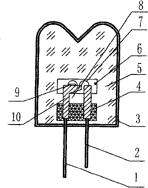
[0020] Embodiment 3. In this embodiment, the LED semi-finished product obtained in Embodiment 1 is subjected to spectroscopic and color separation detection, and the finished product is integrated into the light source board in a series (parallel) manner, and the lamp holder with the electrode column After conductively connecting one end of the lamp with one end of the light source board, it is connected to the lamp tube in a leak-free sealed connection, and then the optical coupling coolant is injected into the lamp tube, and then the other end of the lamp holder with the electrode column is conductively connected to the light source board , implement leak-free sealing connection with the lamp tube, so as to manufacture a power type LED fluorescent lamp tube lamp with integrated light source, optical coupling, cooling liquid and heat conduction.

Embodiment 4

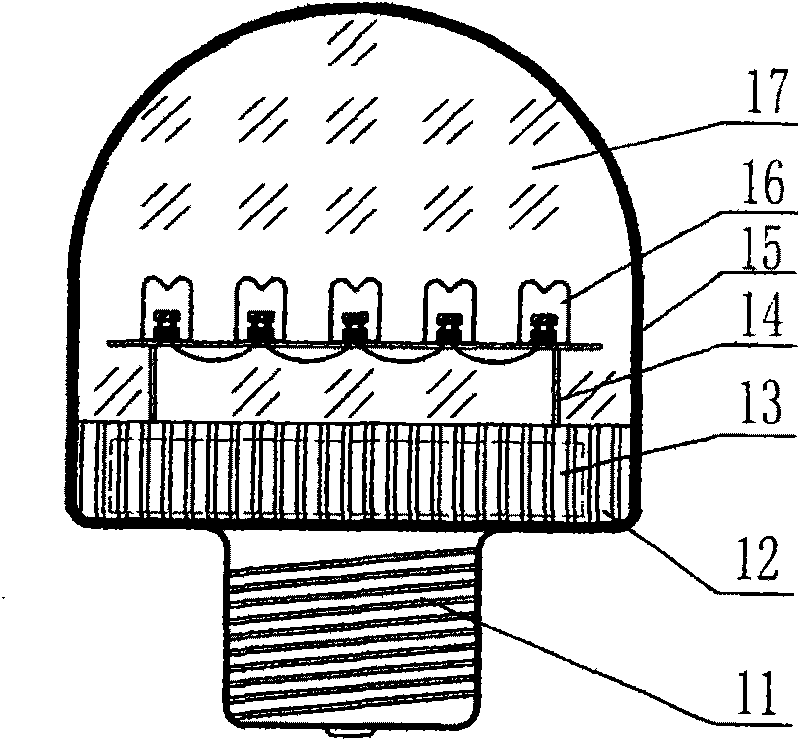
[0021] Embodiment 4. In this embodiment, the LED semi-finished products obtained in Embodiment 1 are subjected to spectroscopic and color separation detection, or other high-power LED single lamp products are integrated into the light source board in a series (parallel) manner. Complete integrated LED semi-finished products. The shell of the light source output end is integrated with LED semi-finished products, silicone sealing strips, heat dissipation shells and the inlet of the optically coupled coolant pump, and assembled into a whole without leakage, and the pipe is connected to the output end of the pump through the inner wall of the lamp support tube, and the input end of the pump The tubing is connected to the light-coupled coolant in the cooling bath. Start the pump to pump the light-coupled coolant into the combined sealed chamber until the light-coupled coolant overflows from the overflow port at the other end of the overflow port, and the connected return pipe overf...


PUM


Abstract

The invention provides an LED lamp radiating with optically coupled cooling liquid. An excellent heat-conducting optically coupled cooling liquid is filled between the luminous body of the outgoing end of the LED lamp and an enclosed shell so as to complete leakage-free encapsulation. Excellent heat-conducting properties and excellent optical characters of the optically coupled cooling liquid are used for realizing the improvement of the excellent heat conduction and optical characters between the luminous body of the LED lamp and the shell. When the radiating effect is needed to further improve, the optically coupled cooling liquid is forced to complete adequate heat exchange in a cold pool in the manner of pumping in the cold optically coupled cooling liquid and overflowing the hot optically coupled cooling liquid so that the junction temperature of the luminous body is maintained below 125 DEG C, so as to completely improve the radiating conditions of the luminous body in the LED lamp, prolong the service life of the LED lamp radiating with optically coupled cooling liquid with power LED integrated light source and the outgoing effect of the outgoing end.

Description

Technical field: [0001] The invention relates to an LED lighting fixture after high-density integration of a single lamp power type LED, especially a kind of light projection direction at the front end of the LED light source. Medium convective heat exchange, LED lamps filled with optically coupled coolant (commonly known as refrigerant) for heat dissipation, which have high transparency and high refractive index characteristics and can realize forced convective heat exchange under the action of external power. Background technique: [0002] Currently used LED lamps, as the brightness of high-density integrated power LED light sources continues to increase, the current density continues to increase (currently has reached 135Lm / w), so heat dissipation has become a very important issue in the integration and application of high-density integrated power LED light sources. The outstanding problem is that in order to keep the surface heat balance temperature of the single lamp po...

Claims


Application Information

Patent Timeline
IPC IPC(8): F21S2/00F21V29/00F21Y101/02F21V29/83
Inventor 陈炜旻
Owner 陈炜旻
Why Eureka
Try Eureka