X ray phase contrast tomography
A phase-contrast imaging and X-ray technology, applied in the field of X-ray radiation imaging, can solve problems such as low contrast and tissue stacking, and achieve the effects of reducing dose, improving quality, and fast and simple inspection process
- Summary
- Abstract
- Description
- Claims
- Application Information
AI Technical Summary
Problems solved by technology
Method used
Image
Examples
Embodiment 1
[0122] A specific embodiment of X-ray phase-contrast tomography is given below by taking the scanning manner of an arc track as an example.
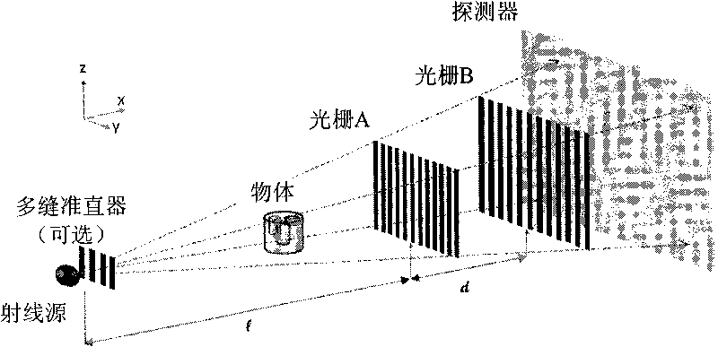
[0123] In the case of this embodiment, the object to be inspected remains fixed, and the X-ray source is fixed on the same support as the detector of the grating subsystem (including double gratings) and the detection unit, as above Figure 10 shown. The source, grating subsystem, and detector remain relatively stationary during data acquisition. In order to meet the parameter requirements of formula (4), it is necessary to adjust the distance between the X-ray source and the double grating. This can be done by fixing the ray source and the second grating B, and adjusting the position of the first grating A in the Z direction. The movement of the first grating A in the Z direction can be completed by controlling the actuating structure of the control device of the system, and the precision is on the order of microns. Similarly, the X-...
Embodiment 2
[0128] In an exemplary case, the detector portion of the detection unit and the grating subsystem remain stationary while the ray source moves linearly, as in Figure 11a , 11b shown. In this case, the mechanical movement of the system is simpler. Compared with the arc track scanning method, its effective scanning angle is smaller under the condition of detectors of the same size.
[0129] During the data acquisition process of a position state, the inspected object (such as mammary gland), the double grating and the detector remain stationary, and the ray source moves in a straight line, such as Figure 11a shown. Wherein, the ray source can move on the trajectory at equal intervals, or in an equiangular manner. In the equiangular mode, the movement interval of the object is determined by the angular interval θ and the distance L from the ray source to the sample, H=Lsinθ. In the fixed detector scanning mode, the angular sampling interval θ is smaller than that of the ar...
Embodiment 3
[0134] This embodiment describes the linear trajectory scanning mode, which is characterized in that the ray source, the grating subsystem and the detector remain relatively stationary, and move relatively linearly with the object to be detected, as shown in FIG. 12 . In this mode, the system structure is simple and does not contain relatively complex rotation movements. Depending on the application environment, such as Figure 12a As shown, there are two equivalent methods for the linear trajectory method: the ray source and the grating subsystem remain stationary, and the sample moves along a linear trajectory; the sample does not move, and the ray source and the grating subsystem remain relatively stationary and perform linear motion.
[0135] Taking the first movement mode as an example, the object to be inspected moves on a linear trajectory, stops at different positions and remains still, completes a phase step scan, and obtains one or more projection images through info...
PUM
 Abstract
Description
Claims
Application Information
 - R&D
- Intellectual Property
- Life Sciences
- Materials
- Tech Scout
- Unparalleled Data Quality
- Higher Quality Content
- 60% Fewer Hallucinations
Browse by: Latest US Patents, China's latest patents, Technical Efficacy Thesaurus, Application Domain, Technology Topic, Popular Technical Reports.
© 2025 PatSnap. All rights reserved.Legal|Privacy policy|Modern Slavery Act Transparency Statement|Sitemap|About US| Contact US: help@patsnap.com


