Optical switching device and control method thereof

A control method and optical switch technology, applied in the field of network communication, can solve the problems of loss change, large absorption loss, and difficulty in improving the extinction ratio of optical switches, and achieve the effect of low loss and high extinction ratio

Active Publication Date: 2010-06-09
HUAWEI TECH CO LTD +1
View PDF0 Cites 28 Cited by
  • Summary
  • Abstract
  • Description
  • Claims
  • Application Information

AI Technical Summary

Problems solved by technology

[0010] Since the existing technology uses the carrier dispersion effect of silicon materials to realize the fast switching of optical switches, but the plasma dispersion effect of carriers causes the refractive index change of silicon materials (phase changes that can be transformed for waveguide transmission) at the same time , the accompanying absorption loss is also very large; and because the loss introduced by the modulation changes seriously and the symmetry of the light intensity of the transmission arm 3 and the transmission arm 4, it is difficult to improve the extinction ratio of the optical switch

Method used


Image

  • Optical switching device and control method thereof
  • Optical switching device and control method thereof
  • Optical switching device and control method thereof

Examples


Embodiment Construction

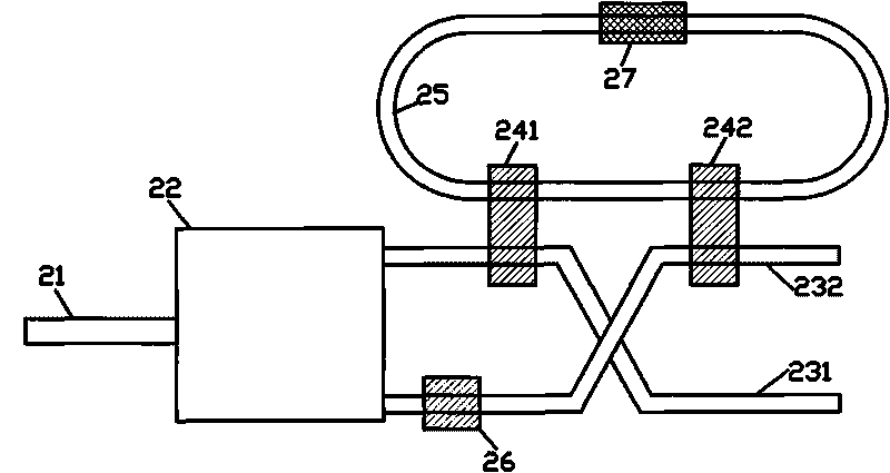
[0029] An embodiment of the present invention provides an optical switch device, such as figure 2 Shown includes: an input waveguide 21, a 1*2 beam splitter 22, two output waveguides 23 (for the method of description, here the two output waveguides are defined as output waveguides 231 and output waveguides 232), the 1*2 beam splitter The input end of device 22 is connected with input waveguide 21, and the two output ends of this 1*2 beam splitter 22 are connected with two output waveguides 23 respectively; The device also includes: at least one microring resonator 25 and setting at least two Coupling region 24 (for the method described, the coupling region arranged on the output waveguide 231 is defined as coupling region 241 here, and the coupling region arranged on output waveguide 232 is defined as coupling region 242), the two output waveguides are respectively in The provided at least two coupling regions 24 are connected to the microring resonator 25 . Wherein, the mic...


PUM


Abstract

The execution mode of the invention provides an optical switching device and a control method thereof, which belong to the field of network communication. The device comprises an input wave guide, a 1*2 beam splitter and two output wave guides; the input end of the 1*2 beam splitter is connected with the input wave guide, and the two output ends of the 1*2 beam splitter are respectively connected with the two output wave guides; the device also comprises at least one microring resonator and is provided with at least two coupling regions; and the two output wave guides are respectively connected with the arranged coupling regions and the microring resonator. The device and the method have the advantages of less waste and high extinction ratio.

Description

technical field [0001] The invention relates to the field of network communication, in particular to a method for controlling an optical switch device and the optical switch device. Background technique [0002] With the increase of the amount of communication information, due to the "electronic bottleneck" effect, the use of traditional optical switching (OCS) technology has shown shortcomings such as low bandwidth utilization and limited speed. The trend of the Internet protocol (IP over DWDM) technology used is becoming more and more obvious, so the demand for the corresponding high-speed switching technology is becoming more and more urgent, and the use of all-optical packet switching (Optical Packet Switching, OPS) is the development direction. Optical switch is the key device of all-optical communication network, and it has been paid attention to by people all the time. [0003] The prior art provides an optical switch device, such as figure 1 As shown, it includes: ...

Claims


Application Information

Patent Timeline
Patent Type & Authority Applications(China)
IPC IPC(8): G02B6/35
Inventor 操时宜江晓清杨建义王帆王明华
Owner HUAWEI TECH CO LTD
Why Eureka
Try Eureka