Pressure quenching mold for obtaining quality-controllable intensified heat-treated superhigh intensity steel plate

An ultra-high-strength, steel plate technology, applied in the field of heat treatment, can solve the problems of not forming a guideline for the direction of the press-quenching die, and not clearly proposing how to guide the design according to certain rules

Active Publication Date: 2010-06-16
CENT IRON & STEEL RES INST
View PDF2 Cites 10 Cited by
  • Summary
  • Abstract
  • Description
  • Claims
  • Application Information

AI Technical Summary

Problems solved by technology

[0002] In the prior art, the equipment for pressure-quenching ultra-high-strength steel plates such as bullet-proof steel plates for enhanced heat treatment, regardless of the roll-type quenching equipment or the vertical quenching equipment, cannot realize the quality control of steel plates with different thickness specifications on the same set of equipment. controlled pressure quenching
Utility Model Patent ZL200320103136.2 A Pressure Quenching Device for Thin Bulletproof Steel Plate Although a pressure quenching device for thin gauge bulletproof steel pla

Method used


Image

  • Pressure quenching mold for obtaining quality-controllable intensified heat-treated superhigh intensity steel plate
  • Pressure quenching mold for obtaining quality-controllable intensified heat-treated superhigh intensity steel plate
  • Pressure quenching mold for obtaining quality-controllable intensified heat-treated superhigh intensity steel plate

Examples


Embodiment 1

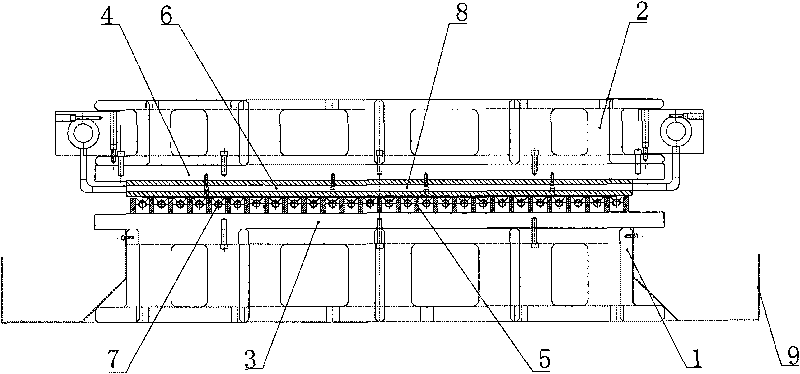
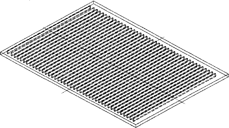
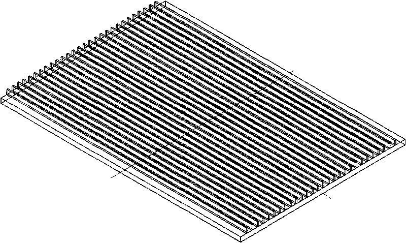
[0022] according to figure 2 , image 3 As shown in the design style of the cooling water channel, after the upper and lower parts are pressed together to form a well-shaped cooling circulation water channel in the mold, the intersection of the upper and lower ribs can be considered as the soft point. Among them, the intersection of the upper and lower ribs in Example 1-1 is 20×20 mm squares, a total of 81 squares; the intersection of upper and lower ribs in Example 1-2 is 10×10 mm squares, a total of 361 squares.

Embodiment 1-1

[0024] Embodiment 1-1, na=20×20×81=32400mm 2 =0.0324m 2

Embodiment 1-2

[0025] Embodiment 1-2, na=10×10×361=36100mm 2 =0.0361m 2

[0026] Putting this binary value into formula 1, it can be seen that when the sheet thickness influence coefficient r t , Cooling water flow Q w and press quenching force p are constant, the quenching effect of embodiment 1-1 is better than embodiment 1-2, this is because embodiment 1-1 has adopted less number of soft spots and area when designing the press quenching mold implementation plan.


PUM


Abstract

A pressure quenching mold for obtaining a quality-controllable intensified heat-treated superhigh intensity steel plate belongs to the technical field of heat treatment. The mold comprises an upper mold and a lower mold, wherein the lower mold consists of a lower platform, a lower mold mounting plate, a lower vertical rib plate, a lower mold water inlet pipe and a water tank; the lower vertical rib plate, the lower mold water inlet pipe and the water tank are arranged on the lower mold mounting plate, and then the lower mold mounting plate is fixed on the lower platform through a fastening screw; the upper mold consists of an upper platform, an upper mold mounting plate, an upper vertical rib plate and an upper mold water inlet pipe; and the upper vertical rib plate and the upper mold water inlet pipe are arranged on the upper mold mounting plate, and then the upper mold mounting plate is fixed on the upper platform through the fastening screw. When pressure quenching operation is performed, a slide block on a pressure machine moves downwards to drive the upper mold to be enclosed with the lower mold, and cooling water sprayed from the lower mold water inlet pipe and the upper mold water inlet pipe circularly flows in a water passage to perform pressure quenching on the steel plate. The water tank reclaims the sprayed cooling water for later cycle use. The mold has the advantage that: the intensified heat-treated superhigh intensity steel plate produced by the mold has controllable quality and excellent performance.

Description

technical field [0001] The invention belongs to the technical field of heat treatment, and in particular relates to a pressure quenching mold for obtaining ultra-high-strength steel plates with controllable quality and enhanced heat treatment. Background technique [0002] In the prior art, the equipment for pressure-quenching ultra-high-strength steel plates such as bullet-proof steel plates for enhanced heat treatment, regardless of the roll-type quenching equipment or the vertical quenching equipment, cannot realize the quality control of steel plates with different thickness specifications on the same set of equipment. Controlled pressure quenching. Utility Model Patent ZL200320103136.2 A Pressure Quenching Device for Thin Bulletproof Steel Plate Although a pressure quenching device for thin gauge bulletproof steel plate is proposed that can effectively guarantee the shape and flatness of the steel plate without quenching deformation, However, it has not been clearly pr...

Claims


Application Information

Patent Timeline
IPC IPC(8): C21D1/673
CPCY02P10/20
Inventor 董瀚陈鹰惠卫军张英建时捷张涛
Owner CENT IRON & STEEL RES INST
Why Eureka
Try Eureka