Central cavity stable fire tangential combustion chamber

A combustion chamber and cavity technology, applied in the direction of combustion chambers, continuous combustion chambers, combustion methods, etc., can solve the problem of affecting combustion efficiency and outlet temperature distribution, the tangential momentum of the compressor outlet airflow is not well utilized, and the length is shortened, etc. problem, to achieve the effect of long residence time, compact structure and reduced length

Inactive Publication Date: 2010-06-16
BEIHANG UNIV
View PDF0 Cites 28 Cited by
  • Summary
  • Abstract
  • Description
  • Claims
  • Application Information

AI Technical Summary

Problems solved by technology

[0006] In addition, due to the pressure of reducing the size and weight of aviation gas turbines, the length of the conventional combustion chamber is also greatly shortened, and the atomization, evaporation, mixing and combustion of fuel are all carried out in the axial direction, and the too short length of the combustio

Method used


Image

  • Central cavity stable fire tangential combustion chamber
  • Central cavity stable fire tangential combustion chamber
  • Central cavity stable fire tangential combustion chamber

Examples


Embodiment Construction

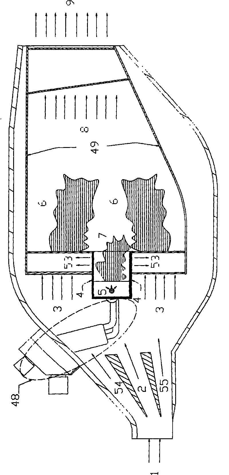
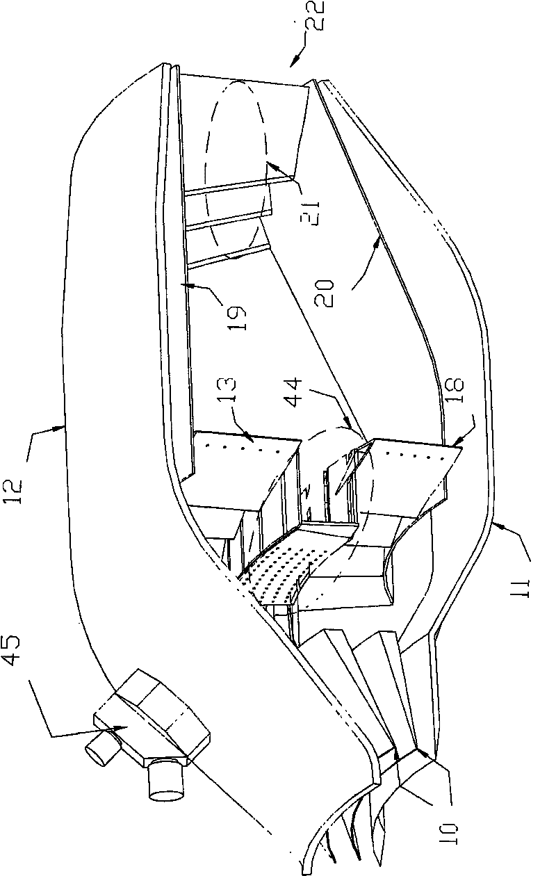
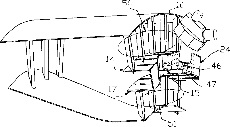
[0038] Such as figure 1 , 2 3, the combustion chamber of the present invention consists of a split diffuser 10, a combustion outdoor casing 12, a combustion chamber casing 11, a central cavity rear step pre-combustion stage 44, and an outer ring bluff body flame stabilizer main combustion stage 50. The main combustion stage 51 of the inner ring bluff body flame stabilizer, the fuel supply system 48, the inner flame tube 19, the outer flame tube 20, and the outlet support plate 21 are composed.

[0039] The combustion chamber designed by the present invention adopts the concept of staged combustion. The combustion gas is all pre-burned from the central cavity to the back step to the pre-combustion stage 44, the outer ring bluff body flame stabilizer main combustion stage 50 and the inner ring bluff body flame stabilizer main combustion stage 51 Supply, do not use traditional mixing holes. The central cavity rear step pre-combustion stage 44 adopts the central cavity rear step annu...


PUM

PropertyMeasurementUnit
Apertureaaaaaaaaaa
Apertureaaaaaaaaaa
Angleaaaaaaaaaa

Abstract

The invention discloses a central cavity stable fire tangential combustion chamber, which consists of a shunting type diffuser, a combustion chamber external cartridge receiver, a central cavity rear step pre-combustion stage, an outer ring blunt body flame stabilizer main combustion stage, an inner ring blunt body flame stabilizer main combustion stage, a fuel supply system, an inner flame tube,an outer flame tube and an outlet supporting plate. An air flow with a deflection angle is diffused into the combustion chamber by the shunting type diffuser; the central cavity pre-combustion stage consists of a rear step, a top plate, a nozzle, a tangential slot inner ring and a tangential slot outer ring, and in the pre-combustion stage, the flame is stabilized by a low-speed recirculation zone generated by the rear step; the inner ring and the outer ring blunt body flame stabilizer main combustion stages consist of the inner ring, the outer ring and blunt body stabilizers with deflection angles, the high temperature and high pressure fuel jetted out of the inner ring and outer ring blunt body flame stabilizers is mixed with air, is ignited by the pre-combustion stage, and is burnt stably in a low-speed zone after a blunt body; and the outlet supporting plate is arranged between the inner flame tube and the outer flame tube and has an included angle with the axial line of the combustion chamber, and the outlet gas of the combustion chamber has an deflection angle. The central cavity stable fire tangential combustion chamber realizes tangential flow and tangential combustion while ensuring stable combustion for providing power; besides, the structure is simplified, and the weight of the combustion chamber is reduced.

Description

Technical field [0001] The invention is a gas turbine combustor with tangential intake, combustion and exhaust. While ensuring tangential flow and combustion, the combustor and the entire gas turbine are shortened in length, compact in structure and reduced in weight. Background technique [0002] The basic performance and structural distribution of modern gas turbine combustion chambers have reached a very high level. However, for modern gas turbine combustion chambers, there are still some problems and challenges. The development and application of new materials, new processes, new structures, and new concepts are Guarantee its source of continuous progress. [0003] The combustion organization of the conventional gas turbine combustor is based on the airflow mainly flowing in the axial direction, using the local low-speed recirculation zone of the main combustion zone to form a continuous ignition source for stable combustion, and adopting an appropriate fuel supply method to at...

Claims


Application Information

Patent Timeline
IPC IPC(8): F23R3/20F23R3/52
Inventor 薛鑫林宇震许全宏张弛刘高恩
Owner BEIHANG UNIV
Why Eureka
Try Eureka