
Manufacturing method of flash memory

A technology of flash memory and manufacturing method, which is applied in semiconductor/solid-state device manufacturing, electrical components, circuits, etc., can solve the problems of increasing resistance and reducing the cut-off current of devices, and achieve the goals of reducing cut-off current, increasing distance, and increasing width Effect

Active Publication Date: 2011-06-22
SHANGHAI HUAHONG GRACE SEMICON MFG CORP
View PDF0 Cites 0 Cited by
  • Summary
  • Abstract
  • Description
  • Claims
  • Application Information

AI Technical Summary

Problems solved by technology

For example, since the thickness of the oxide film on the active region will also be thickened at the same time, the resistance of the source and drain will increase only by thickening the oxide film layer. In the same situation, the cut-off current of the device is reduced

Method used


Image

  • Manufacturing method of flash memory
  • Manufacturing method of flash memory
  • Manufacturing method of flash memory

Examples


Embodiment Construction

[0029] Such as Figure 9 As shown, the flash memory preparation process of the present invention comprises the following steps:

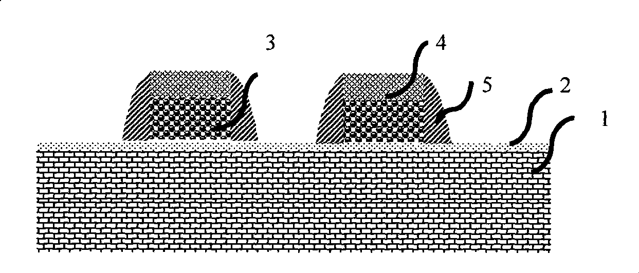
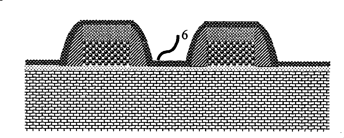
[0030] Firstly, a polysilicon gate is formed using a conventional process and the sidewall is etched. Its structure is as follows: Figure 10 As shown, there is a gate oxide layer 2 on a silicon substrate 1, a polysilicon gate 3 is grown on the gate oxide layer, a hard mask layer 4 is formed on the polysilicon gate, and sidewalls 5 are formed on the side of the polysilicon gate structure. Then, if Figure 11 As shown, after the traditional gate nitride film spacer 5 is etched, an oxide film 9 with a certain thickness is deposited.

[0031] Then, if Figure 12 As shown in , the oxide film layer grown in the previous step is etched back, the hard mask layer is etched above the gate structure, and the silicon substrate is etched in other areas on the surface of the silicon wafer to form a gentle oxide film sidewall . This increases the distance fr...


PUM


Abstract

The invention discloses a manufacturing method of a flash memory, comprising the following steps after forming a grid electrode silicon nitride side wall: 1) depositing a first layer of oxidation film on silicon wafer surface; 2) reverse etching the first layer of oxidation film, etching to a hard masking layer above grid electrode structure, and etching to a silicon substrate on other regions ofthe silicon wafer surface to form a smooth oxidation film side wall; 3) depositing a second layer of oxidation film on the silicon wafer surface; 4) carrying out ion implantation of source leakage; 5) adopting wet etching technology, and simultaneously removing the first layer of oxidation film and the second layer of oxidation film; and 6) depositing an interlayer membrane film on the surface ofthe silicon wafer. Under the condition of changing no other properties of a device, the invention lowers the cut-off current of the device.

Description

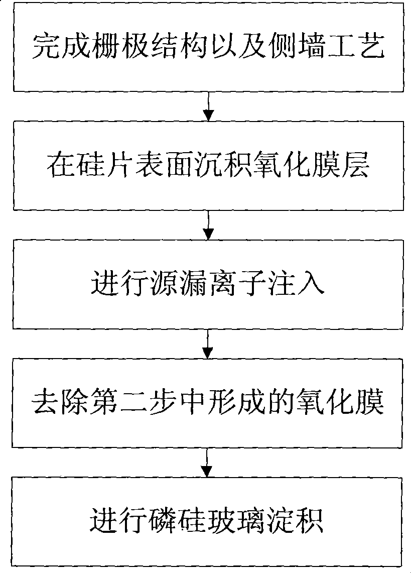
technical field [0001] The invention relates to the field of integrated circuit manufacturing technology, in particular to a method for making a flash memory in the field of integrated circuit manufacturing. Background technique [0002] In flash memory devices of 0.13um and below, memory structures with self-aligned contact holes are generally used. In order to reduce the cut-off current of the device without affecting the process window of the subsequent etching of the self-aligned contact hole. The larger the distance between the nitride film sidewalls of the two devices, the larger the process window for subsequent self-aligned contact hole etching. [0003] In order to increase the subsequent self-aligned contact hole etching process window, such as figure 1 As shown, the existing process method for preparing flash memory includes the following process steps: [0004] First, if figure 2 As shown, the gate structure and the side wall process are completed. There is...

Claims


Application Information

Patent Timeline
Patent Type & Authority Patents(China)
IPC IPC(8): H01L21/8247H01L21/336
Inventor 吕煜坤孙娟袁苑
Owner SHANGHAI HUAHONG GRACE SEMICON MFG CORP
Learn More