
Slope and peak integrated control circuit for insulated gate bipolar transistor

A bipolar transistor, comprehensive control technology, applied in electrical components, electronic switches, pulse technology, etc., can solve the problems of low reliability, difficulty in accurately locating the start and end times of the Miller effect, and complexity, so as to improve reliability. performance, improved control and protection effects, and the effect of simple circuit topology

Active Publication Date: 2010-06-16
TSINGHUA UNIV
View PDF0 Cites 4 Cited by
  • Summary
  • Abstract
  • Description
  • Claims
  • Application Information

AI Technical Summary

Problems solved by technology

Gate signal delay adjustment, especially online adjustment, the control circuit must be able to adapt to the IGBT characteristics that change with temperature rise, so it is more complicated and less reliable
Miller capacitive servo control is also difficult in practice, because it is difficult to accurately locate the start and end moments of the Miller effect
The method of tracking the voltage reference value also includes specific measures, but either the number of IGBTs in series is limited, or the control circuit uses chips such as microprocessors and high-performance operational amplifiers, which are more complicated, less reliable and more expensive. high
The control circuit based on the gate RCD auxiliary circuit is simple and has high reliability, but the biggest problem is that it will cause significant oscillation of the IGBT collector-emitter voltage, and may even cause IGBT malfunction, endangering the safety of the equipment

Method used


Image

  • Slope and peak integrated control circuit for insulated gate bipolar transistor
  • Slope and peak integrated control circuit for insulated gate bipolar transistor
  • Slope and peak integrated control circuit for insulated gate bipolar transistor

Examples


Embodiment 1

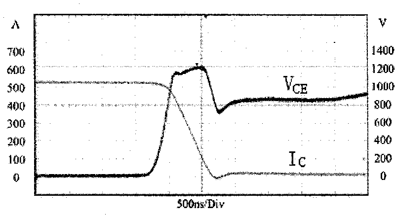
[0026] Such as image 3 As shown, when two 1.7kV / 800A insulated gate bipolar transistors are used in series, they are turned off when the DC voltage is 1.7kV and the load current is 520A (impeding inductive load), the reference value of the collector-emitter voltage slope is 3000V / μs, - When the reference value of the peak value of the emitter voltage is 1.2kV, the control effect of the slope and peak integrated control circuit of the present invention. The slopes of both IGBTs are controlled, and the collector-emitter voltage V CE The peak value is controlled by the peak value of the first stage when it reaches about 1.1kV, and the waveform turns, and then it is controlled by the peak value of the second stage when it reaches about 1.2kV. Among them, V CE is the collector-emitter voltage; I C is the collector current. Experiments have proved that the comprehensive control of slope and peak value is effective, the IGBT always works within a safe range, and the dynamic volt...

Embodiment 2

[0028] Such as Figure 4 As shown, when two 1.7kV / 800A insulated gate bipolar transistors are used in series, they are turned off when the DC voltage is 1.7kV and the load current is 470A (impeding inductive load), the reference value of the collector-emitter voltage slope is 3000V / μs, - The control effect of the slope and peak integrated control circuit of the present invention under the condition that the reference value of the peak value of the emitter voltage is 1.1kV, and the turn-off signals of the two IGBTs differ by 400 ns. The slopes of both IGBTs are controlled, and the collector-emitter voltage V of the early-turn-off IGBT CE The peak value reaches 1.1kV first, and is controlled by the peak value of the first stage and the second stage respectively, and the waveform turns twice; then the collector-emitter voltage V of the late-turn-off IGBT CE The peak value also reaches 1.1kV, and is controlled by the peak value of the first stage and the second stage respectively...

Embodiment 3

[0030] Such as Figure 5 As shown, eight 1.7kV / 800A insulated gate bipolar transistors connected in series are used to turn off (impedance inductive load) when the DC voltage is 7.3kV and the load current is 700A. The reference value of the collector-emitter voltage slope is 3000V / μs. - When the reference value of the peak value of the emitter voltage is 1.2kV, the control effect of the integrated slope and peak value control circuit of the present invention. The slope and peak value of the eight insulated gate bipolar transistors are all controlled, all of them work within the safe range, and the dynamic voltage equalization of all the insulated gate bipolar transistors is realized.


PUM


Abstract

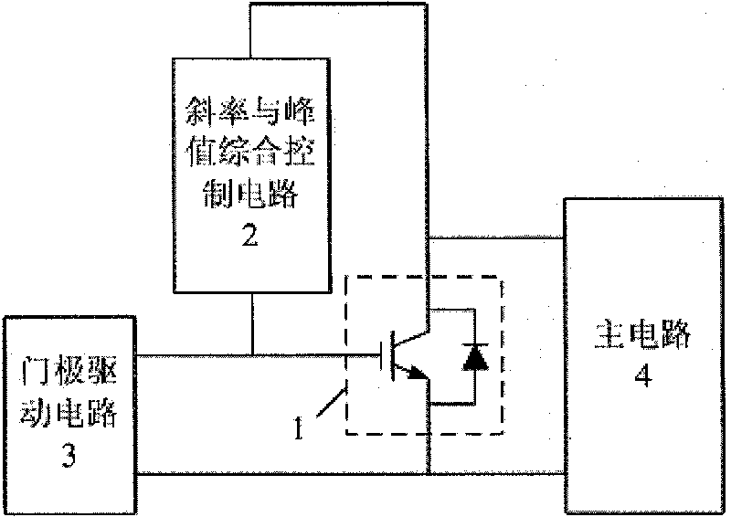
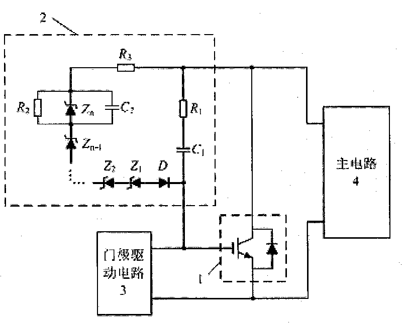
The invention relates to a slope and peak integrated control circuit for an insulated gate bipolar transistor, which is characterized by comprising an insulated gate bipolar transistor, a slope and peak integrated control circuit, a gate drive circuit and a main circuit, wherein the gate of the insulated gate bipolar transistor is connected with the output end of the slope and peak integrated control circuit and one output end of the gate drive circuit in parallel; the input end of the slope and peak integrated control circuit is connected with the collector of the insulated gate bipolar transistor and one input end of the main circuit in parallel; and the other output end of the gate drive circuit is connected with the emitter of the insulated gate bipolar transistor and the other input end of the main circuit in parallel. In the invention, because resistors, capacitors, Zener diodes and other small simple components are used for forming the slope and peak integrated control circuit which is directly crossed between the collector and the gate of the insulated gate bipolar transistor, the topological structure of the circuit is simplified, and the reliability of the circuit is improved. The invention can be widely applied to various devices in the fields of electric power and electronics.

Description

technical field [0001] The invention relates to a control circuit of a power semiconductor device, in particular to a slope and peak integrated control circuit for an insulated gate bipolar transistor (IGBT, Insulated Gate Bipolar Transistor) in the field of power electronics. Background technique [0002] IGBT is currently the most widely used turn-off power electronic device. It is used in everything from low-voltage electrical appliances to high-voltage power transmission and distribution equipment, from civil power facilities to military equipment, and from traditional thermal power generation to new energy power generation. In ordinary applications, the operation requirements can be met by using ordinary IGBT control and protection circuits. However, in some special application fields, IGBT devices must carry very high voltage and high current, and even require IGBT to operate in series, such as high-voltage electronic switches, high-voltage pulse power supplies, high-v...

Claims


Application Information

Patent Timeline
IPC IPC(8): H03K17/567
Inventor 张春朋刘博超姜齐荣童陆园
Owner TSINGHUA UNIV
Learn More