Quadruple frequency-based scheme for realizing base station passive full duplex millimeter wave RoF link

A millimeter-wave, full-duplex technology, applied in the field of full-duplex link communication, can solve the problems of expensive external modulator and local oscillator signal source, high requirements for working environment, high cost of light source, etc., to achieve strong Actual operability, simplification of base station structure and functions, effect of base station cost reduction

Inactive Publication Date: 2010-06-16
BEIJING UNIV OF POSTS & TELECOMM
0 Cites 29 Cited by

AI-Extracted Technical Summary

Problems solved by technology

However, the frequency of the external modulator and local oscillator signal source required by the system based on the linear external modulation method to generate optical millimeter signals should not be lower than the frequency of the generated millimeter wave signal, and the required optical external modulator and local oscillator The frequency of the signal increases with the frequency of the generated millimeter-wave signal, and the high-frequency external modulator and local oscillator signal source are relatively expensive
The nonlinear external modulation technology can reduce the requirements of these two indicators. The optical carrier suppression (OCS, optical carrier suppression) modulation technology reported in the literature can...

Abstract

The invention discloses a quadruple frequency-based scheme for realizing a base station passive full duplex millimeter wave RoF link, which is mainly used for remote transmission of a wireless signal between a base station and a central station in a Gb/s broadband millimeter wave communication system. The scheme is as shown in an attached drawing. A local oscillator with a frequency of fD/4 drives a lithium niobate Mach-Zehnder modulator to produce a light carrier with a frequency interval of fD/2 and two second-order sidebands. One sideband is separated by an FBG to realize single wave carrier modulation of a downlink data signal. The light carrier is transmitted to the base station through an optical fiber, and the light carrier and a double-frequency light millimeter wave signal with a frequency of fD are separated by the Mach-Zehnder modulator with a delay time difference of 1/fD. The former is reserved as an uplink light source, and the latter produces a millimeter wave signal with the frequency of fD through photoelectric conversion, and the signal is transmitted to a user through an antenna. The uplink millimeter wave signal is processed by envelope detection to acquire a baseband signal, loaded onto a reserved light wave by a low-speed optical modulator and sent back to the central station by the optical fiber. The scheme has a plurality of advantages, so that the scheme has good application prospect.

Application Domain

Technology Topic

Image

  • Quadruple frequency-based scheme for realizing base station passive full duplex millimeter wave RoF link
  • Quadruple frequency-based scheme for realizing base station passive full duplex millimeter wave RoF link
  • Quadruple frequency-based scheme for realizing base station passive full duplex millimeter wave RoF link

Examples

  • Experimental program(1)

Example Embodiment

[0022] Specific implementation method
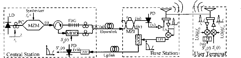
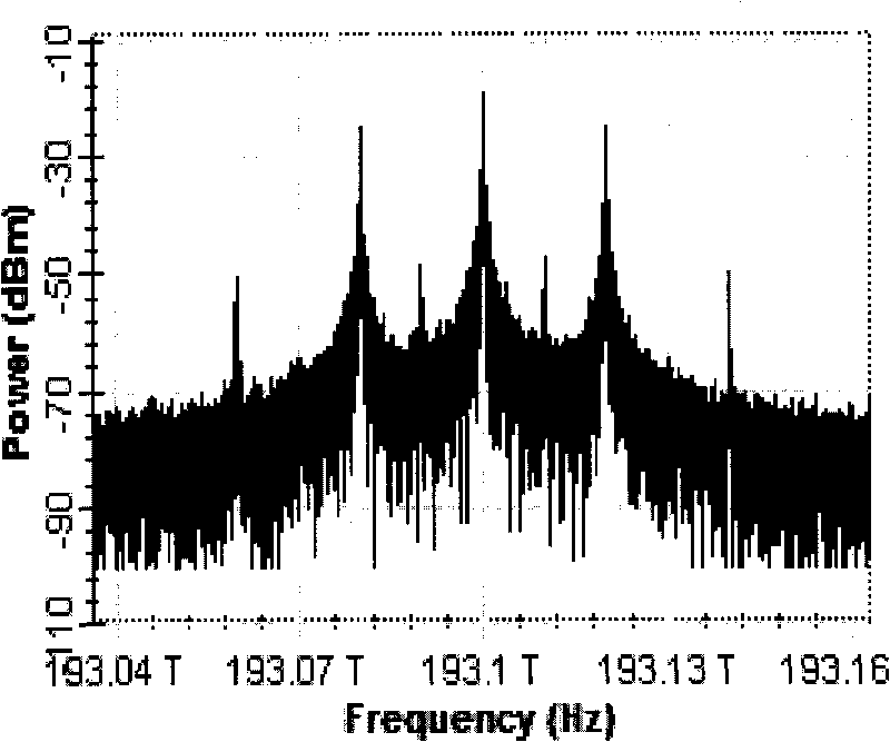
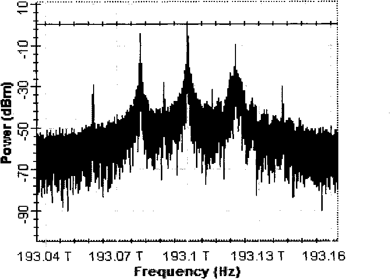
[0023] The working wavelength of the laser is λ, the present invention takes 1552.5nm (193.1THz) as an example, and the downlink millimeter wave signal rate is f D The present invention takes 40GHz as an example, the corresponding frequency of the lithium niobate Mach-Zehnder modulator is 10GHz, the DC bias voltage is 0, the peak-to-peak voltage of the RF local oscillator is 8V, and the resulting spectrum is as figure 2 Shown. The second sideband is separated by an FBG with a center wavelength of 1552.12nm and a bandwidth of 30GHz, and a binary NRZ baseband signal with a rate of 5Gbit/s is loaded onto the sideband through an intensity modulator with a response rate of 5GHz, and adjusted by a polarization controller After the polarization direction is made parallel, the optical coupler is combined, and the spectrum measured by the spectrometer is as image 3 Shown. In the base station, the optical millimeter wave signal and the optical carrier are separated by the MZI with a delay difference of 25 ps between the two arms. The optical millimeter wave signal and the optical carrier spectrum output from the two ports of the MZI are as follows Figure 4 Shown. Before transmission through optical fiber, a photodetector with a response frequency of 50GHz converts a 40GHz optical millimeter wave signal into an electrical signal. Its radio frequency spectrum and eye diagram are as follows Image 6 Shown. by Image 6 The radio frequency spectrum can be seen: the photocurrent is mainly composed of baseband signals and 40GHz millimeter wave signals, the latter is what we need. In order to verify the performance of the optical millimeter wave signal, a 40GHz local oscillator signal is used to coherently demodulate the 40GHz photocurrent signal, and the demodulated baseband signal eye diagram is as follows Figure 7 Shown.
[0024] The generated optical millimeter wave signal is injected into a standard single-mode fiber, and after 40km transmission and amplified to 10dBm by an erbium-doped fiber amplifier (EDFA), the eye pattern of the radio frequency signal is coherently demodulated by the 40GHz photocurrent 5Gbit/s baseband signal eye diagram such as Figure 8 , Picture 9 Shown. It can be seen from the eye diagram that although the fiber dispersion has a certain degree of degradation to the signal quality, after 40km of fiber transmission, the opening of the eye diagram can still ensure the correct detection of the signal.
[0025] In the uplink, the reserved optical carrier (1552.5nm) is intensity modulated by the uplink baseband signal (binary NRZ) at a rate of 5Gbit/s. The spectrum and eye diagram in the back-to-back case are as follows Picture 10 Shown. The eye pattern of the 5Gbit/s uplink baseband signal after 40km uplink transmission to the central station is as follows Picture 11 Shown. It can be seen from the eye diagram that the openness of the eye diagram can still ensure correct signal detection.
[0026] In summary, the present invention uses a conventional lithium niobate Mach-Zehnder modulator to simultaneously generate 4 times the frequency downlink optical millimeter wave signal and uplink optical carrier at the central station, and simultaneously realizes single-carrier modulation of the signal. To reduce the influence of fiber link dispersion, this solution not only reduces the frequency requirements of the optical modulator and RF local oscillator in the optical millimeter wave generating equipment, but also the generated optical millimeter wave signal has good long-distance (~40km) transmission performance. Migrating the uplink light source in the base station to the central station greatly simplifies the structure of the base station without additional downlink bandwidth. The invention is simple and easy to implement, and requires low component frequency requirements, which greatly reduces the difficulty and cost of implementing a Gbit/s broadband millimeter wave full-duplex RoF link.
[0027] In a word, the above-mentioned embodiment is only an example of the present invention, and is not only used to limit the protection scope of the present invention. It should be pointed out that for those of ordinary skill in the art, the content disclosed in the present invention is also Several equivalent deformations and replacements can be made, and the frequency range of the millimeter wave is not limited to the 40 GHz in the above example. These equivalent deformations and replacements and adjustment of the frequency range should also be regarded as the protection scope of the present invention.

PUM

no PUM

Description & Claims & Application Information

We can also present the details of the Description, Claims and Application information to help users get a comprehensive understanding of the technical details of the patent, such as background art, summary of invention, brief description of drawings, description of embodiments, and other original content. On the other hand, users can also determine the specific scope of protection of the technology through the list of claims; as well as understand the changes in the life cycle of the technology with the presentation of the patent timeline. Login to view more.

Similar technology patents

Carbon nanotube/silicon/graphene composite material, preparation method thereof and lithium ion battery

InactiveCN104064736AExcellent energy storage performance and cycle performanceSimple equipmentCell electrodesSecondary cellsCvd grapheneCarbon nanotube
Owner:OCEANS KING LIGHTING SCI&TECH CO LTD +2

Classification and recommendation of technical efficacy words

  • Simple equipment
  • Strong practical operability
Why Eureka
Try Eureka