

Fuel injection nozzle of opposite-spraying atomizing internal combustion engine
A technology of fuel injectors and internal combustion engines, applied in mechanical equipment, engine components, machines/engines, etc., can solve problems such as power consumption, achieve low cost, improve energy saving and emission indicators, and simple principles
Inactive Publication Date: 2010-06-23
么烈
View PDF0 Cites 6 Cited by
- Summary
- Abstract
- Description
- Claims
- Application Information
AI Technical Summary
Problems solved by technology
However, the ultra-high fuel pressure not only requires a high-quality fuel system, but also consumes a certain amount of power consumption.
Method used
View moreImage
Smart ImageViewing Examples

Examples
Embodiment Construction
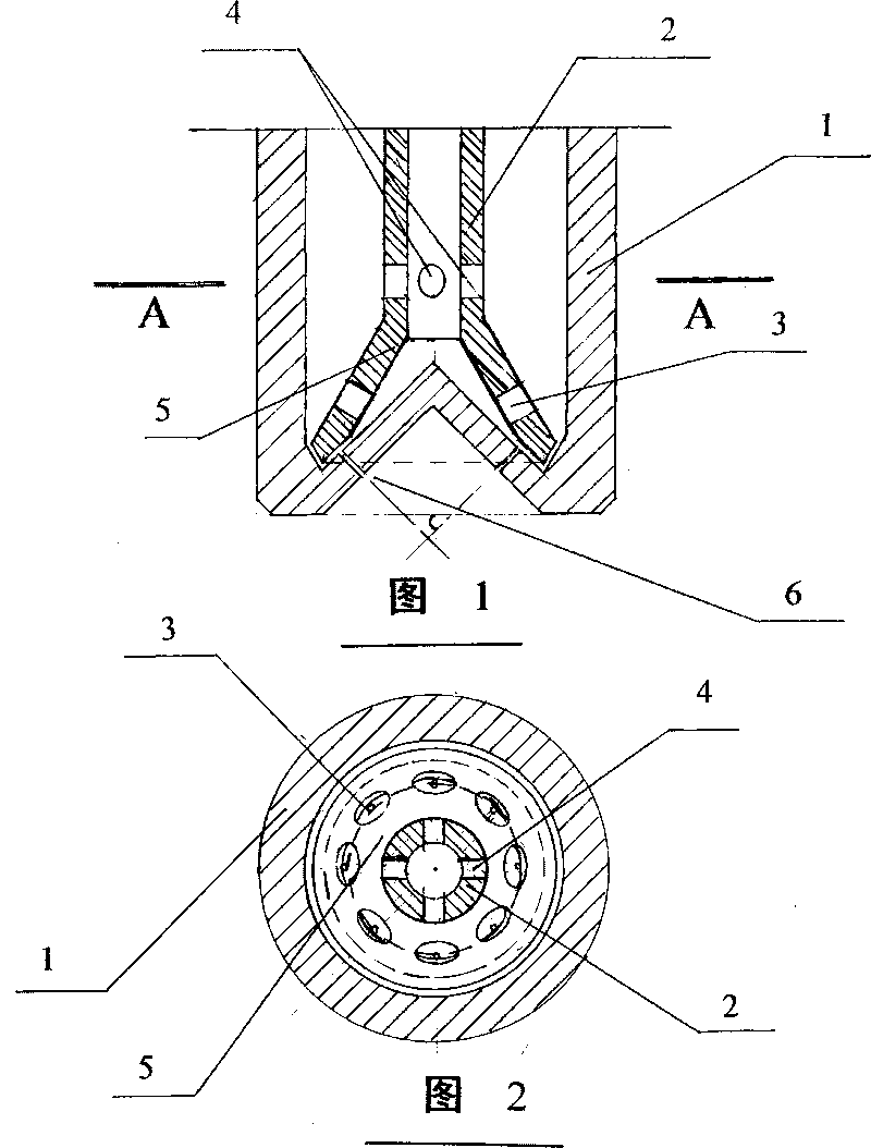
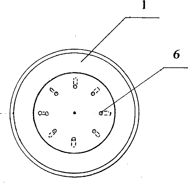
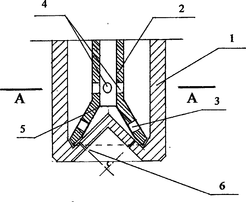
[0014] Based on the existing fuel injectors of various diesel engines and gasoline engines, it is used as a design reference. Retain its normal structure and function, change the needle valve part into a cup-shaped tubular valve, and design the number and diameter of the spray holes according to the requirements. The installation size of the newly designed fuel injector is the same as that of the original fuel injector, or approximately the same.
Login to View More PUM
 Abstract
The invention provides a fuel injection nozzle of an opposite-spraying atomizing internal combustion engine. On the basis of a traditional fuel injection nozzle, the original needle valve is changed to a cup-shaped tubular valve which is sleeved on a conical valve seat to control a plurality of oil injection holes on the valve seat. The bottom of the fuel injection nozzle and the valve seat are correspondingly provided with conical pits, the oil injection holes correspondingly arranged on the valve seat inject oil beams with the same horizontal included angle, a plurality of oil beams are oppositely impacted at the same potion, thus, the primarily atomized fuel particles are secondarily atomized. By using the fuel injection nozzle of the invention, the construction is simple, the manufacture is easy, and more excellent atomization effect can be obtained under the same oil injection pressure. The fuel injection nozzle is capable of replacing the traditional fuel injection nozzles and widely applied to the prior engines. The fuel injection nozzle can be made into the fuel injection nozzle of diesels or the fuel injection nozzle of gasoline engines and can be applied to the fuel injection nozzle of jet engines and mechanical equipment needing to atomize fuel.
Description
[0001] Field [0002] The invention relates to a fuel injection nozzle of a counter-spray internal combustion engine, and relates to the design and manufacture technology of the gasoline engine fuel injection nozzle and the design and manufacture technology of the diesel engine fuel injection nozzle. In particular, it relates to the design and manufacturing technology of the spray fuel atomizing nozzle. Background technique [0003] With the development and progress of society, the energy consumption and emission indicators of traditional engines can no longer meet the higher requirements of modern society for engines. Improving the quality of combustible mixed gas and improving combustion conditions are important measures for energy saving and emission reduction. In order to pursue higher atomization performance and optimize combustion effect, a new technology of high-pressure common rail electronically controlled fuel injection has been adopted on diesel engines, and its fu...
Claims
Login to View More Application Information
Patent Timeline
 Patent Type & AuthorityApplications(China)
IPC IPC(8): F02M61/18
Inventor么烈
Owner么烈