
Device for measuring six-dimensional position poses of object

A technology of object and pose, which is applied in the field of measuring the six-dimensional pose of objects, can solve the problem of high cost and achieve the effects of low cost, light weight and high measurement accuracy

Inactive Publication Date: 2010-06-23
SHENYANG INST OF AUTOMATION - CHINESE ACAD OF SCI
View PDF14 Cites 121 Cited by
  • Summary
  • Abstract
  • Description
  • Claims
  • Application Information

AI Technical Summary

Problems solved by technology

[0012] In order to overcome the shortcomings of the prior art, such as high cost, or the need for a two-degree-of-freedom turntable, or the need for a high-resolution camera system, the application of the present invention extends the close-range vision processing method proposed in the prior art to the existing laser tracker, 3D pose can be obtained accurately and conveniently

Method used


Image

  • Device for measuring six-dimensional position poses of object
  • Device for measuring six-dimensional position poses of object
  • Device for measuring six-dimensional position poses of object

Examples


Embodiment 1

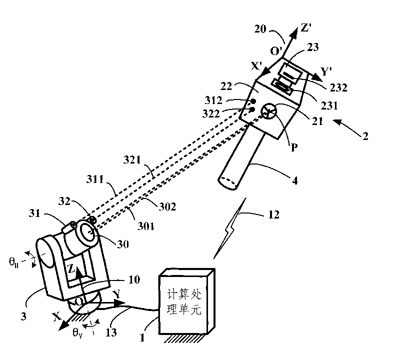
[0037] Such as figure 1 Shown is the first example of the six-dimensional pose measurement device proposed by the present invention, which is composed of a computing processing unit 1 , a receiver 2 and a laser tracker 3 . The laser tracker 3 is usually fixedly installed on the ground. The receiver 2 is installed on the moving object 4 whose six-dimensional pose is to be measured through a connecting piece or directly. In the figure, the receiver coordinate system 20 is O'-X'Y'Z', fixed on the receiver, while the global coordinate system 10 is O-XYZ, usually fixed on the laser tracker, and the moving object coordinate system is O m -X m Y m Z m (not shown), fixed on the moving object 4. Since the pose of the receiver coordinate system 20 relative to the moving object coordinate system is always fixed and can be obtained by a calibration method, measuring the six-dimensional pose of the moving object 4 is equivalent to measuring the receiver coordinate system 20 relative t...

Embodiment 2

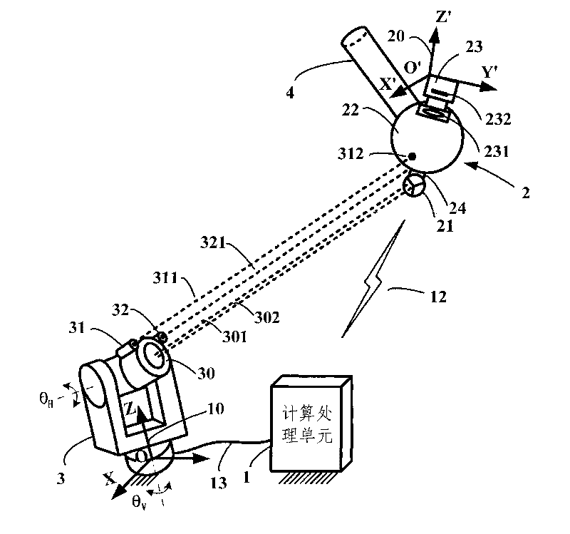
[0083] image 3 Shown is the second example of the six-dimensional pose measurement device proposed by the present invention. The difference from the first example is that the projection panel 22 on the receiver 2 adopts a spherical shape, and the imaging unit 23 is located on the inside of the projection panel; the projection panel 22 is provided with a magnetic support 24; The prism reflective ball can be reliably adsorbed on the magnetic support 24, and the operator can manually adjust the orientation of the retroreflector 21. The above two modifications can obtain a larger three-dimensional attitude measurement range. Of course, the magnetic support 24 can also be designed as a manual turntable or an automatic turntable with one degree of freedom or two degrees of freedom. Both the rotation axes of the manual turntable and the automatic turntable pass through the center of the prism reflective ball, which can keep the position of the center of the prism reflective ball re...

Embodiment 3

[0085] Figure 4 Shown is the third example of the six-dimensional pose measurement device proposed by the present invention. This example is mainly suitable for small-scale measurements. The rangefinder 30 on the laser tracker 3 is a structured light position sensor measured by triangulation method, which can be LK-G500 from Keyence Corporation of Japan, and the measurement range is 250mm-1000mm. Since triangulation is not suitable for measuring highly reflective surfaces, the retroreflector 21 is replaced in this example by a reflective patch. In this example, the projection panel 22 is made of a scattering and light-transmitting material, so that part of the incident laser light is diffusely reflected and part of it is diffusely transmitted. Therefore, the diffuse reflection function of the reflective patch can be realized by the projection panel 22 . In this example, the projection panel 22 is a spherical surface, but it may also be a plane or other curved surfaces. Sin...


PUM


Abstract

The invention discloses a device for measuring six-dimensional position poses of an object, which consists of a laser tracking instrument, a receiver, a computing unit and at least one small-sized laser light emitter, wherein the computing unit and the laser tracking instrument are fixedly arranged on the ground surface; the receiver is arranged on a moving object to be measured; the laser tracking instrument and the receiver communicate with the computing unit; the small-sized laser light emitter is arranged on the laser tracking instrument; a horizontal intersection angle and a pitching intersection angle of the laser tracking instrument are controllable, and the laser tracking instrument is provided with a laser distance measuring instrument; and the laser distance measuring instrument and the small-sized laser light emitter project laser light to a projection panel of the receiver respectively. The laser tracking instrument acquires a three-dimensional position of the receiver, and the computing unit solves three-dimensional postures of the receiver corresponding to a fixed coordinate system on the ground surface according to an azimuth angle of the laser tracking instrument and image data of laser faculae on the projection panel. The device can continuously measure moving objects or static objects in a large space, has the advantages of high precision, quick measuring speed, low cost and convenient arrangement, and can replace an expensive laser tracking instrument for measuring the six-dimensional poses.

Description

technical field [0001] The invention relates to the measurement technology of the six-dimensional pose of an object in a relatively large space, specifically a three-dimensional coordinate measurement using a laser tracker, using a laser beam to generate a light spot on a receiver and performing close-distance image processing technology and parallel measurement The principle is a device for measuring the three-dimensional attitude of an object. It can be widely used in occasions where the six-dimensional pose of an object needs to be measured. It can measure both stationary objects and moving objects, and can replace expensive six-dimensional pose measurement laser trackers. Background technique [0002] High-precision measurement of the three-dimensional position (x, y, z) and three-dimensional attitude (α, β, γ) of a moving object has a wide demand in the industry. [0003] In order to measure the six-dimensional pose of an object moving in a large range, a global positi...

Claims


Application Information

Patent Timeline
IPC IPC(8): G01B11/00G01S17/66
CPCG01B11/03G01S17/875G01B11/002
Inventor 罗振军田永利
Owner SHENYANG INST OF AUTOMATION - CHINESE ACAD OF SCI
Learn More