Method and device for controlling peak power output of power supplier

A technology of maximum output power and power supply, which is applied in the direction of control/regulation systems, instruments, and adjustment of electrical variables, etc. It can solve problems such as loss of output power, current sensing waveforms that cannot touch the current limit value waveforms, and difficulties, etc., to achieve Effect of reducing output power error range

Inactive Publication Date: 2010-06-23
RICHTEK TECH
View PDF1 Cites 5 Cited by
  • Summary
  • Abstract
  • Description
  • Claims
  • Application Information

AI Technical Summary

Problems solved by technology

Although this method is simple and direct, it also has the following disadvantages: (1) Although this control is a single method to apply to all applications (one size fits all), the built-in waveform is based on a set of most commonly used power supply range determined by system parameter calculations
Although the system designer can obtain better output power convergence (convergence) by fine-tuning the parameters to conform to the built-in waveform, however, some parameters such as performance, electromagnetic interference (EMI), heat, etc. must be compromised, These parameters will affect the primary inductor, current sense resistor, gate driver resistor, etc., and the output power will usually deviate from the original design, which forces the system designer to spend more time or add additional components to solve the problem
In addition, it is often found in practice that some system designs achieve better output power convergence when

Method used


Image

  • Method and device for controlling peak power output of power supplier
  • Method and device for controlling peak power output of power supplier
  • Method and device for controlling peak power output of power supplier

Examples


Embodiment Construction

[0036] The present invention will be further described below in conjunction with embodiment and accompanying drawing.

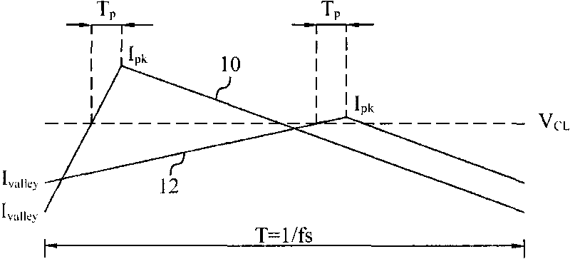
[0037] see now Figure 4 , Figure 4 The current sense signal 14 is shown amplified by m times, which indicates that the corresponding inductor current stores energy into the desired maximum output power

[0038] P o max = η · L · f s 2 [ ( V pk m · R cs ) 2 - ( V valley m · ...


PUM


Abstract

The invention discloses a method for controlling peak power output of power supplier. The power supplier determines the working period of a power switch by comparing a current sensing signal and a dynamically adjustable current limiting threshold, the current sensing signal represents the magnitude of current in the power switch. The invention is characterized in that the method comprises the following steps: A. supplying the present current limiting threshold; and B. estimating the next current limiting threshold according to the present current limiting threshold and the current sensing signal. The method and device for controlling peak power output of power supplier in the invention have the advantage of narrowing error range of output power of power supplier.

Description

technical field [0001] The present invention relates to a power supply, in particular to a control method and device for the power supply. Background technique [0002] A flyback power supply is a buck / boost converter that uses a two-winding inductor to provide electrical isolation and non-inverting output. Its energy storage and conversion is through the The charging and discharging of the secondary coil inductance. For a universal input (universal input) flyback converter, it usually operates in continuous conduction mode (CCM) at low input voltage (low line), and operates at high input voltage (high line) In discontinuous conduction mode (discontinuous conduction mode; DCM), to obtain better efficiency. However, the propagation delay of the flyback power supply causes the maximum output power of the power supply to vary with the magnitude of the input voltage (line voltage). Propagation delay is the cumulative result from the current-limit comparator, to the pulse-widt...

Claims


Application Information

Patent Timeline
IPC IPC(8): G05F1/67
Inventor 黄培伦张光铭
Owner RICHTEK TECH
Why Eureka
Try Eureka