
Method of pulse compression for cascaded optical parametric amplification system

An optical parameter and amplification system technology, applied in the laser field, can solve the problems of lack of pulse compression, high price, and inability to be widely used, and achieve the effect of improving beam quality

Inactive Publication Date: 2010-06-23
SHANGHAI INST OF OPTICS & FINE MECHANICS CHINESE ACAD OF SCI
View PDF0 Cites 6 Cited by
  • Summary
  • Abstract
  • Description
  • Claims
  • Application Information

AI Technical Summary

Problems solved by technology

The disadvantage is that this technology does not have the function of pulse compression, and the single attosecond pulse compressed by the 30fs to 40fs laser pulse emitted by the titanium sapphire laser cannot generate the cycle level required by the experiment.
Using this method, the output pulse energy has been improved, but it is still only a few hundred microjoules. In addition, this method requires dispersion compensation for the pulse with a central wavelength of 1425nm, but at present, the infrared compression technology is still immature and suitable for The chirped mirror for compensating dispersion in this region is still in the research and development stage, and the price is too expensive to be widely used

Method used


Image

  • Method of pulse compression for cascaded optical parametric amplification system
  • Method of pulse compression for cascaded optical parametric amplification system
  • Method of pulse compression for cascaded optical parametric amplification system

Examples


Embodiment Construction

[0023] The present invention will be further described below by embodiment, but should not limit protection scope of the present invention with this.

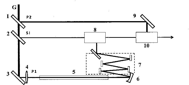
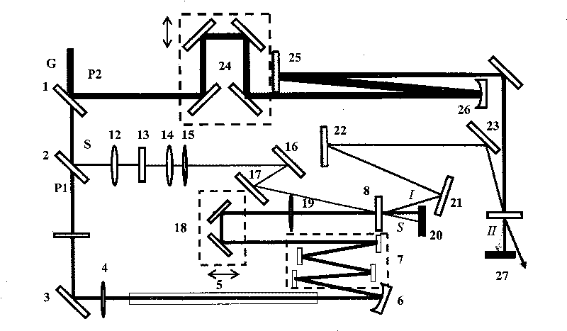
[0024] see first figure 1 , figure 1 It is a structural schematic diagram of the pulse compression method of the cascaded optical parametric amplification system of the present invention. It is an embodiment of the present invention. As can be seen from the figure, the present invention is a method for pulse compression of a cascaded optical parametric amplification system. The laser pulse G incident on the cascaded optical parametric amplification system is about 40fs, and the center frequency is around 800nm. The first beam splitter 1 and the second beam splitter 2 are divided into the first-stage pump light P1, the second-stage pump light P2 and the signal light SI. The first-stage pump light P1 is reflected by the mirror 3 and enters the lens 4 to focus, and then enters the hollow fiber 5 filled with inert gas. Due to the...


PUM


Abstract

The invention discloses a method of pulse compression for a cascaded optical parametric amplification system, which is characterized in that: a hollow-fiber compression device is added to the light path of first-class pump light, and the pulse width of the first-class pump light output by the hollow-fiber compression device is compressed to a cycle magnitude, first-class pump light and signal light of the cycle magnitude pass through a first-class optical parametric amplifier, and generates the first-class signal light and first-class idling light, meanwhile, the first-class signal light or the first-class idling light are selected as the signal light of a second-class optical parametric amplifier. The invention avoids the immature infrared compression technology and utilizes the mature compression technology near 800 nm to reach the same expected effect, and the energy loss is greatly reduced, meanwhile, the light-source output performance of OPA system is better, and the invention is beneficial for generating higher harmonic wave, even is beneficial for the application of the single attosecond pulse experiment.

Description

technical field [0001] The invention relates to a pulse compression method for a cascaded optical parameter amplification system, which uses a hollow fiber pulse compression device for the first-stage pump light of the optical parameter amplification system, and belongs to the field of laser technology. It is characterized in that the pumping light of the first stage in the cascaded OPA is compressed by using a hollow fiber compression system filled with inert gas, so that the OPA system finally obtains a laser pulse output with a pulse width equivalent to that of the pumping light of the first stage. This device converts the demand for infrared compression into the demand for visible light compression, optimizes the output pulse of the OPA system, making the pulse width as short as the cycle level, high energy loss and extremely low, high-order harmonic experiment, attosecond pulse generation And other physical experiments provide strong support. Background technique [00...

Claims


Application Information

Patent Timeline
Patent Type & Authority Applications(China)
IPC IPC(8): H01S3/23H01S3/094
Inventor 李冬雪冷雨欣张春梅黄延髓王丁陈晓伟李儒新徐至展
Owner SHANGHAI INST OF OPTICS & FINE MECHANICS CHINESE ACAD OF SCI
Learn More