
Current loop control method of permanent magnet synchronous motor

A technology of permanent magnet synchronous motor and control method, which is applied in the direction of motor generator control, electronic commutation motor control, control system, etc., can solve the problems affecting the control accuracy and dynamic response speed of the permanent magnet synchronous motor control system, and improve the Effects of dynamic running performance, dynamic performance improvement, and control accuracy improvement

Inactive Publication Date: 2010-06-23
重庆红宇精密工业集团有限公司
View PDF5 Cites 13 Cited by
  • Summary
  • Abstract
  • Description
  • Claims
  • Application Information

AI Technical Summary

Problems solved by technology

[0003] The purpose of the present invention is to provide a new current loop control method for permanent magnet synchronous motors, which can effectively solve the problem of motor speed and motor parameters affecting permanent magnet synchronous motors. Key issues such as control accuracy and dynamic response speed of the motor control system

Method used


Image

  • Current loop control method of permanent magnet synchronous motor
  • Current loop control method of permanent magnet synchronous motor
  • Current loop control method of permanent magnet synchronous motor

Examples


Embodiment Construction

[0030] The present invention will be further described below with reference to the accompanying drawings and specific embodiments.

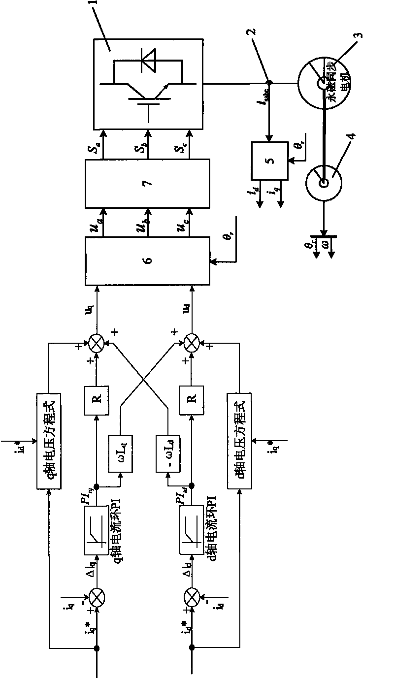
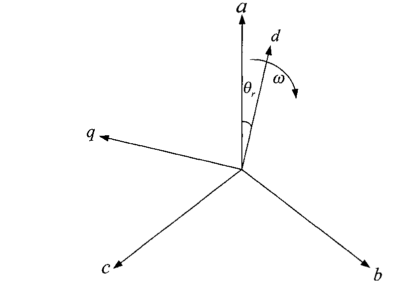
[0031] The current loop control method of the permanent magnet synchronous motor position servo control system for radar, figure 1 It is a schematic diagram of the control method, including the control object permanent magnet synchronous motor 3, a two-level voltage type PWM inverter 1 connected to the stator of the permanent magnet synchronous motor, and a current Hall sensor 2 for three-phase stator current detection, The encoder 4 used to detect the rotor position of the permanent magnet synchronous motor and the control loop for controlling the permanent magnet synchronous motor, the control loop is composed of a feedback signal processing channel and a forward control channel, wherein: the feedback signal processing channel includes abc / dq Rotary coordinate transformation module 5; forward control channel includes dq / abc rotational coordina...


PUM


Abstract

A current loop control method of a permanent magnet synchronous motor relates to the current loop control method of a permanent magnet synchronous motor under the rotor field-oriented synchronous rotating coordinate axes, which comprises: acquiring stator current signal of the motor; detecting the position of the rotor of the motor, and computing the electrical angular velocity and the electrical angle; performing coordinate transformation for the stator current signal of the motor to obtain the d, q axis component of the stator current of the motor; establishing stationary equation set; establishing current loop control equation set; and undergoing coordinate transformation to obtain the switching signal of the motor operation. The invention has the benefit effect that the invention has higher voltage control precision, can meet the requirement of the high precision of different parameter motors within wider velocity range, and has high control precision, good dynamic performance, simple method and wider application range.

Description

technical field [0001] The invention relates to a current loop control method of a permanent magnet synchronous motor under a synchronous rotating coordinate axis system oriented by the rotor magnetic field. Background technique [0002] The key to the vector control of permanent magnet synchronous motor is to effectively control the stator current. The rotor field oriented vector control method is a widely used permanent magnet synchronous motor control method. Its basic principle is to decompose the stator three-phase winding current of the permanent magnet synchronous motor into the synchronous rotation coordinates oriented by the rotor field through the synchronous rotation coordinate transformation. On the shaft system, the d-axis magnetic field current and q-axis torque current of the permanent magnet synchronous motor are obtained by decomposition. The d-axis field current and q-axis torque current of the permanent magnet synchronous motor are decoupled and controlle...

Claims


Application Information

Patent Timeline
IPC IPC(8): H02P21/12H02P21/14H02P21/18
Inventor 张彬邓世刚唐晓春李辉
Owner 重庆红宇精密工业集团有限公司
Learn More