Energy-saving grain drying equipment

A technology for drying equipment and grains, applied in food processing, preservation of seeds by drying, climate change adaptation, etc., can solve the problems of inability to use dry grains, waste of heat energy, environmental pollution, etc., and is conducive to environmental protection and reduces manufacturing cost, the effect of reducing production costs

Inactive Publication Date: 2010-06-30
铁岭粮食烘干设备研究所
View PDF1 Cites 9 Cited by
  • Summary
  • Abstract
  • Description
  • Claims
  • Application Information

AI Technical Summary

Problems solved by technology

[0002]The water vapor produced in the drying tower of the existing grain drying equipment and the flue gas produced by the hot blast stove are generally not fully utilized, resulting in waste of heat energy and pollution to the environment. The reason is: the moisture content of the water vapor is too high, so it can no longer be used to dry food; the smoke contains a lot of toxic and harmful substances, and it cannot be used to dry food.
For the use of grain drying equipment in the cold winter of Northeast my country, the external temperature is low and the air humidity is generally 50%. Because the traditional structure of grain drying equipment simply increases the temperature of the hot air entering the tower, the hot air with high humidity takes a long time to dry grain and consumes a lot of coal. At the same time, when the cold coal enters the grate, the temperature difference between the inside and the outside is large, and the maintenance of the furnace temperature naturally consumes more energy

Method used


Image

  • Energy-saving grain drying equipment
  • Energy-saving grain drying equipment
  • Energy-saving grain drying equipment

Examples


Embodiment Construction

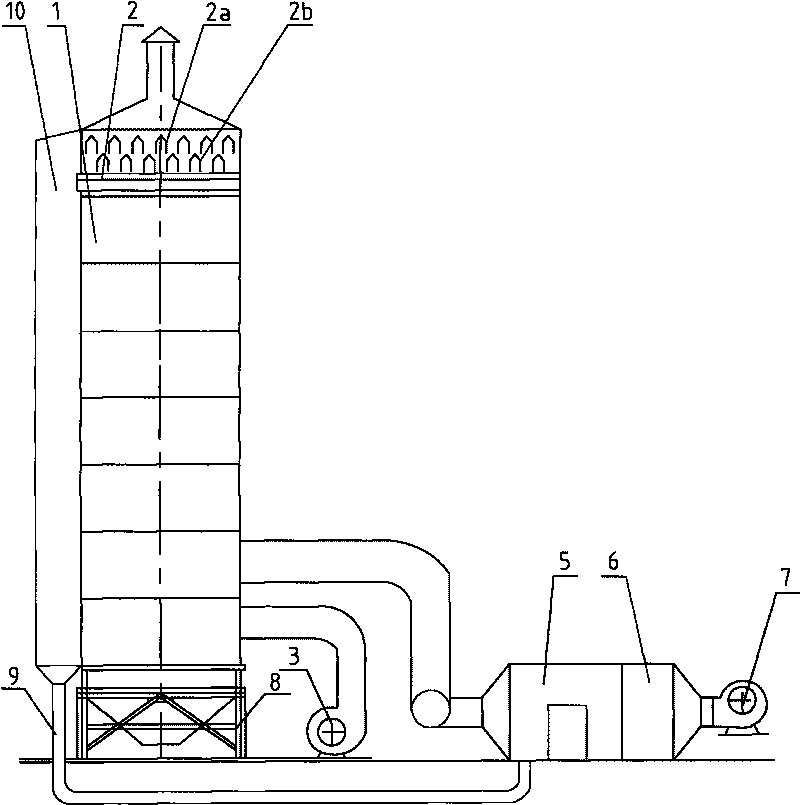
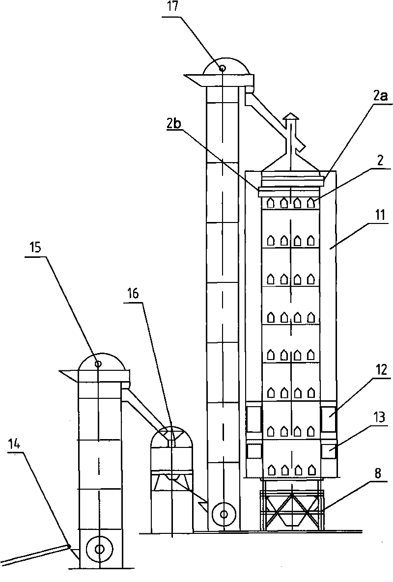
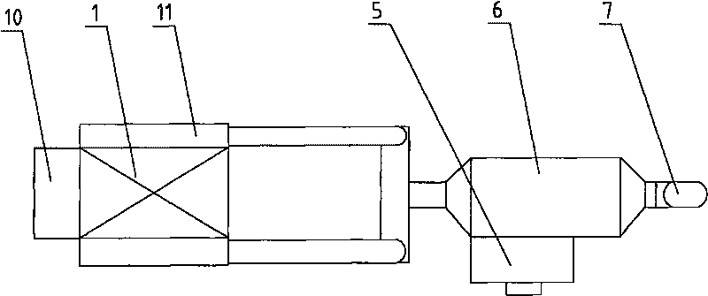
[0015] Depend on Figure 1-4 Shown, main structure of the present invention comprises that it comprises the drying tower 1 that is made up of grain storage section, drying section, slow-down section, cooling section, drying tower feeding device, and this feeding device includes conveyer 14, primary Elevator 15, primary cleaning screen 16 and secondary elevator 17, hot blast stove 6, air cooler 3, four-blade mechanism grain discharge device at the bottom of the drying tower and column tower 8, and three layers are evenly distributed in each section of the drying tower Angular air tanks, wherein the gas outlets of the lowermost angular air tanks 2 in each section are on the side of the drying tower and connected to the waste heat collection chamber 10, which is connected to the water-gas separator 5 through the insulation pipe 9, each The lowermost angular air grooves 2 in the section are perpendicular to the upper angular air grooves 2a, 2b. Both sides of the drying tower are ...


PUM


Abstract

Energy-saving grain drying equipment comprises a drying tower, a feeding device, a hot air furnace, an air cooler, horn-like air tanks, a grain discharge device and a base of the tower. The equipment is characterized in that at least three layers of horn-like air tanks are uniformly distributed in each section of the drying tower; the air outlet ends of the horn-like air tank on the lowermost layer are arranged at one side of the drying tower and are connected with a residual heat collection chamber; the residual heat collection chamber is connected with a water-air separator; the horn-like air tank on the lowermost layer is perpendicular to the horn-like air tanks at the upper side thereof; the air inlet ends of the horn-like air tanks on the two adjacent layers at the upper side are respectively arranged at two sides of the drying tower and are connected with a hot air chamber; a hot air inlet of the hot air chamber is connected with the hot air furnace; a cold air inlet is connected with the air cooler; a flue gas dedusting and purifying device connected with a mixing chamber is arranged on the lower part of a heat exchanger; a residual heat recovery chamber is arranged in a furnace body and is communicated with a residual heat heating chamber which is communicated with a heat exchange chamber; and a blast inlet of the air outside the furnace and a separated air outlet are arranged at the bottom of a flue gas furnace grate. The equipment has the advantages of high efficiency of drying grains, fine quality, small volume, environmental protection, energy saving, etc.

Description

technical field [0001] The invention belongs to the technical field of grain drying equipment, in particular to an energy-saving grain drying equipment. Background technique [0002] The water vapor produced in the drying tower of the existing grain drying equipment and the flue gas produced by the hot blast stove are generally not fully utilized, resulting in waste of heat energy and pollution to the environment. The reason is that the water content of the water vapor is too large to be used Drying food; the flue gas contains a lot of toxic and harmful substances, and it cannot be used for drying food. For the use of grain drying equipment in the cold winter of Northeast my country, the external temperature is low and the air humidity is generally 50%. Because the traditional structure of grain drying equipment simply increases the temperature of the hot air entering the tower, the hot air with high humidity takes a long time to dry grain and consumes a lot of coal. At the ...

Claims


Application Information

Patent Timeline
Patent Type & Authority Applications(China)
IPC IPC(8): A23B9/08
CPCY02A40/90Y02P60/85
Inventor 杨振宇张爽侯婷
Owner 铁岭粮食烘干设备研究所
Why Eureka
Try Eureka