Current generating circuit

A current generation circuit and current generation technology, applied in the direction of regulating electrical variables, control/regulating systems, instruments, etc., can solve problems such as occupation and large layout area, and achieve the effect of miniaturization, area saving, and simplified power management.

Active Publication Date: 2010-06-30
ZHANGJIAGANG KANGDE XIN OPTRONICS MATERIAL
View PDF0 Cites 8 Cited by
  • Summary
  • Abstract
  • Description
  • Claims
  • Application Information

AI Technical Summary

Problems solved by technology

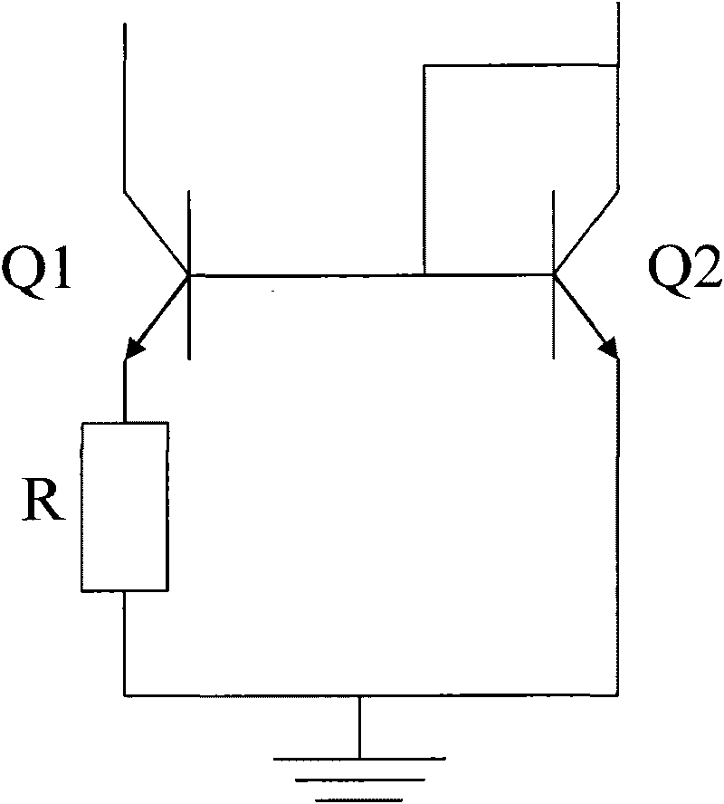
[0011] The present invention solves the problem that the bipolar transistors used in the current generation circuit in the prior art will occupy a large layout area

Method used


Image

  • Current generating circuit
  • Current generating circuit
  • Current generating circuit

Examples


Embodiment Construction

[0026] Embodiments of the present invention implement a current generating circuit using metal-oxide-semiconductor (MOS) transistors. The embodiments of the present invention will be described in detail below with reference to the drawings and examples.

[0027] Figure 5 It is a circuit diagram of an embodiment of the current generation circuit of the present invention to generate positive temperature coefficient current, as Figure 5 As shown, the current generating circuit shown can also be called a PTAT circuit, which generates a current with a positive temperature coefficient, and the shown circuit includes a MOS transistor. Generally, the voltage source provided to the semiconductor circuit includes a high voltage source and a low voltage source, the high voltage source is generally such as 1.8V, 2.5V or 3.3V, and the low voltage source is generally such as 1V or 1.2V. In this example, provide Figure 5 The first voltage source VDD_low of the circuit shown can be a lo...


PUM


Abstract

The invention relates to a current generating circuit which comprises a first current generating unit and a second current generating unit, wherein the first current generating unit comprise an MOS transistor working in a subthreshold area, and is used for generating a current in direct proportion with temperature; the second current generating unit comprises an MOS transistor working in a saturation area, and is used for generating a current irrelevant to the temperature; the difference between the current generated by the second current generating unit and the current generated by the first current generating unit is the third current generated by the current generating circuit. The current generating circuit can meet requirements for semiconductor process miniaturization and system simplification.

Description

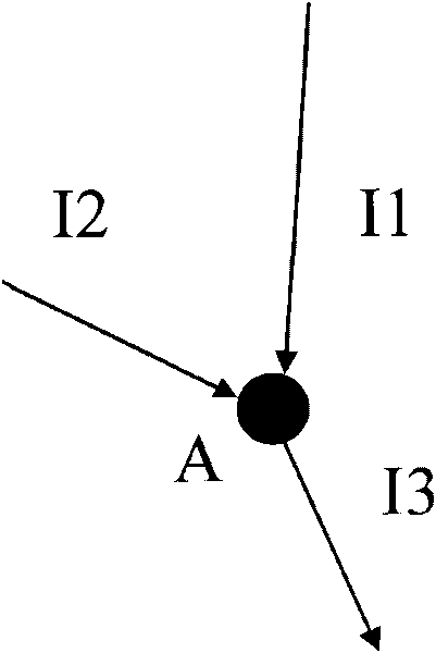
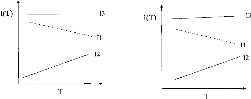
technical field [0001] The present invention relates to semiconductor integrated circuits, and more particularly to current generating circuits. Background technique [0002] As semiconductor technology develops from micron (μm) to nanometer (nm) processes, changes in process conditions have an increasing impact on devices. For example, in a 90nm process, under certain bias conditions, the threshold voltage (threshold voltage) of a metal oxide semiconductor (MOS) transistor will drop sharply by about 70% from a low temperature of -40°C to a high temperature of 125°C. In this case, the current increases significantly at high temperature with a significant decrease in the threshold voltage. Therefore, it is necessary to provide a negative temperature coefficient or a current bias that is inversely proportional to temperature to reduce or eliminate the large current generated at high temperature. [0003] according to figure 1 According to Kirchoff's current law, the sum of ...

Claims


Application Information

Patent Timeline
Patent Type & Authority Applications(China)
IPC IPC(8): G05F3/30
Inventor 杨大为
Owner ZHANGJIAGANG KANGDE XIN OPTRONICS MATERIAL
Why Eureka
Try Eureka