Direct current motor control drive module

A DC motor and drive module technology, applied in the direction of DC motor speed/torque control, excitation or armature current control, control system, etc., can solve problems affecting system performance, weak and small signal interference, large switching noise, etc., and achieve reduction Volume, enhanced applicability, low cost effect

Active Publication Date: 2010-06-30
NO 717 INST CHINA MARINE HEAVY IND GRP
View PDF0 Cites 11 Cited by
  • Summary
  • Abstract
  • Description
  • Claims
  • Application Information

AI Technical Summary

Problems solved by technology

[0003] 1. The switching noise generated is relatively large, which is easy to interfere with other weak and small signals in the equipment and affect system performance; for example: it is easy to interfere with infrared and TV imaging systems of optoelectronic equipment
If the PWM frequency is lower than 2KHZ, sound noise will be generated; if the PWM frequency is increased to more than a dozen kilohertz, although the sound noise is eliminated, the switching peak in the circuit is the main source of interference for the entire electrical equipment, and in severe cases it will cause the system to fail. Realize function
[0004] 2. The power drive components used to drive DC motors will inevitably generate additional heat
In order to make the power drive components work reliably in a high temperature environment, it is generally necessary to install a heat sink to solve the heating problem of the power components. its applicability;

Method used


Image

  • Direct current motor control drive module
  • Direct current motor control drive module
  • Direct current motor control drive module

Examples


Embodiment Construction

[0034] The present invention is further described as follows in conjunction with accompanying drawing and embodiment:

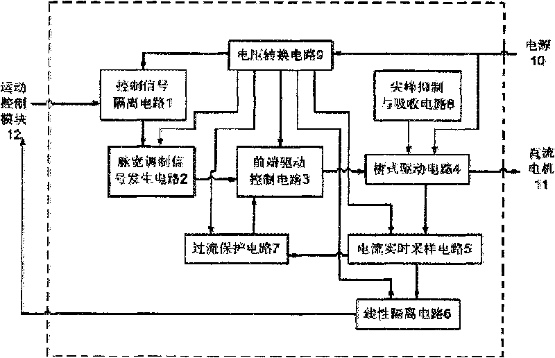
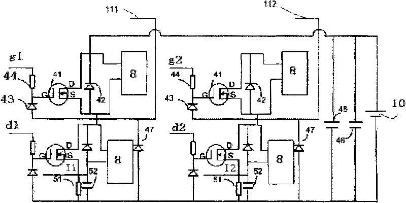
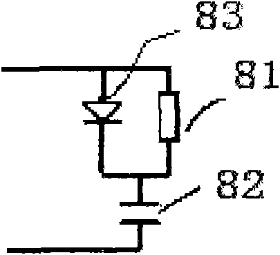
[0035] Such as Figure 1-6As shown, a DC motor control drive module has a peak suppression and absorption circuit 8 for suppressing the peak power of the power drive device 41 in the bridge drive circuit 4 and controlling the noise and heat generation of the power drive device 41; The main circuit of the bipolar motor drive is built by the pulse width modulation signal generation circuit 2, the front-end drive control circuit 3 and the bridge drive circuit 4 in order to stably track the drive of the DC motor in the servo system of the photoelectric equipment and shorten the dynamic response time of the DC motor. ; A current real-time sampling circuit 5, a linear isolation circuit for sampling the current value of the DC motor 11 in real time and isolating the linear output, realizing digital current closed-loop adjustment together with the external motion con...


PUM


Abstract

The invention relates to a direct current motor control drive module, belonging to the electronic technical field of direct current motor control drive. The module comprises a bridge drive circuit, a peak suppression and absorption circuit, a front drive control circuit, a pulse width modulation signal generating circuit, a real-time sampling circuit, a linear isolating circuit, an overcurrent protection circuit, a control signal isolating circuit, and a voltage converting circuit, and the output end of the bridge drive circuit is connected with a direct current motor. The direct current motor control drive module of the invention has the outstanding advantage that the operating requirements of stably tracking the direct current motor drive of a servo system by all photoelectric devices in the sea, land and air fields can be met, and the module is free from heat dissipation, interference and noise, and has low cost, small space usage, quick dynamic response, stable performance, safety and reliability.

Description

technical field [0001] The invention relates to a DC motor control drive module, which belongs to the electronic technical field of DC motor control drive, and is especially suitable for use in sea, land and air equipment with small spaces and special requirements for noise and heat dissipation. Background technique [0002] At present, the existing technology uses pulse width modulation (PWM) technology to drive medium and high-power DC motors, but the disadvantages are: [0003] 1. The generated switching noise is large, which can easily interfere with other weak signals in the equipment and affect system performance; for example, it is easy to interfere with the infrared and TV imaging systems of optoelectronic equipment. If the PWM frequency is lower than 2KHZ, sound noise will be generated; if the PWM frequency is increased to more than a dozen kilohertz, although the sound noise is eliminated, the switching peak in the circuit is the main source of interference for the...

Claims


Application Information

Patent Timeline
IPC IPC(8): H02P7/00H05K7/20H02P7/28
Inventor 胡青张志明姜滨
Owner NO 717 INST CHINA MARINE HEAVY IND GRP
Why Eureka
Try Eureka