Forced internal recirculation type external cooler for catalytic cracking catalyst

A technology of catalytic cracking and external heat extraction, applied in the direction of fluidized bed heat exchanger, heat exchanger type, indirect heat exchanger, etc., can solve the problem of increasing the complexity and manufacturing difficulty of heat extraction equipment, and increasing the risk of difficult application of equipment , reduce the heat exchange efficiency of the heat pipe, etc., to achieve the effect of enhancing the flexibility of adjustment, easy manufacture and application, and simple structure

Active Publication Date: 2010-07-07
CHINA UNIV OF PETROLEUM (BEIJING)
View PDF5 Cites 15 Cited by
  • Summary
  • Abstract
  • Description
  • Claims
  • Application Information

AI Technical Summary

Problems solved by technology

Chinese patent 200720091980.5 proposes an obliquely inserted external heat extractor, in which a series of obliquely inserted heat extraction pipes are arranged, and vertical ribs are arranged on the heat extraction pipes to increase the heat transfer area. The length of the heat pipe in this type of heat extractor is shorter than that of the traditional heat pipe, which is conducive to prolonging its service life. However, the heat extraction efficiency of this inclined heat pipe is generally low, because there is often an air cushion below it, and there will be an air cushion above it. A certain particle fluidization dead zone will greatly reduce the overall heat transfer efficiency of the heat pipe
On the one hand, the setting of the heat-taking pipe isolation tube limits the heat-taking area in the unit space, which is unfavorable for the further improvement of the heat-taking efficiency; Safe and reliable operation, the loss caused by unplanned shutdown due to equipment failure can easily offset the economic benefits brought by the new equipment, the existence of the partition tube will undoubtedly increase the difficulty of equipment manufacturing and potential application risks
The set porous sieve plate and feeding pipe are mainly to facilitate the first introduction of hot catalyst into the bottom of the inner ring area of ​​the partition tube, and to allow the fluidization gas at the bottom to pass through without affecting the flow of the catalyst and then flow from the heat collector. Outflow from the top, this structural design further increases the complexity and manufacturing difficulty of the heat extraction equipment

Method used


Image

  • Forced internal recirculation type external cooler for catalytic cracking catalyst
  • Forced internal recirculation type external cooler for catalytic cracking catalyst
  • Forced internal recirculation type external cooler for catalytic cracking catalyst

Examples


Embodiment 1

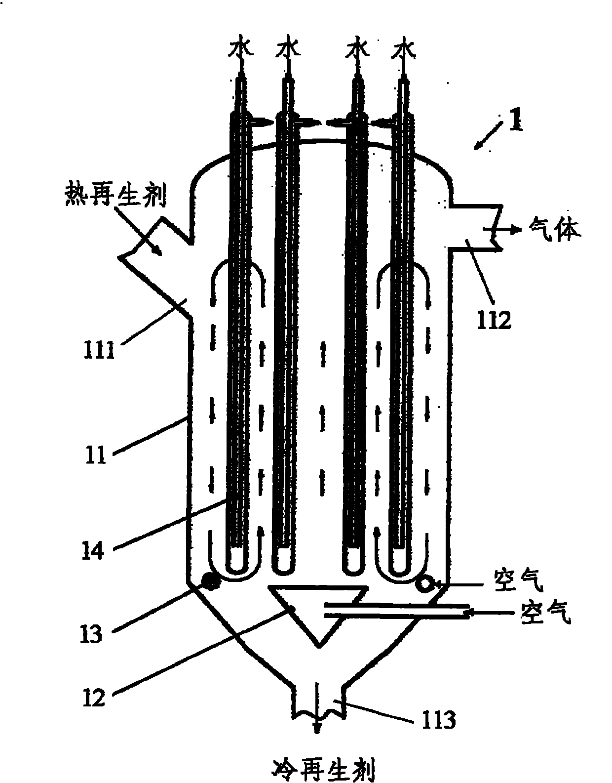
[0040] See figure 1 As shown, the present embodiment provides a forced internal mixing type catalytic cracking catalyst external heat extractor 1, which comprises a round pot-shaped vertical shell 11 (inner diameter is D), and the upper part of the shell is provided with There is a catalyst inlet 111 and a gas outlet 112, and a catalyst outlet 113 is provided at the bottom. The interior of the shell forms the internal heat-taking space of the heat extractor, wherein: at the bottom of the heat extractor 1, there are two valves that can independently pass in fluidized gas and A gas distributor that can individually control the gas flow rate: a central gas distributor 12 arranged in the axial center area inside the heat extractor and a peripheral gas distributor 13 arranged in the side wall area; a gas distributor 12 inside the heat extractor 1 and 13 are provided with a plurality of vertically placed heat-taking pipes 14, and these heat-taking pipes 14 are evenly arranged in the...

Embodiment 2

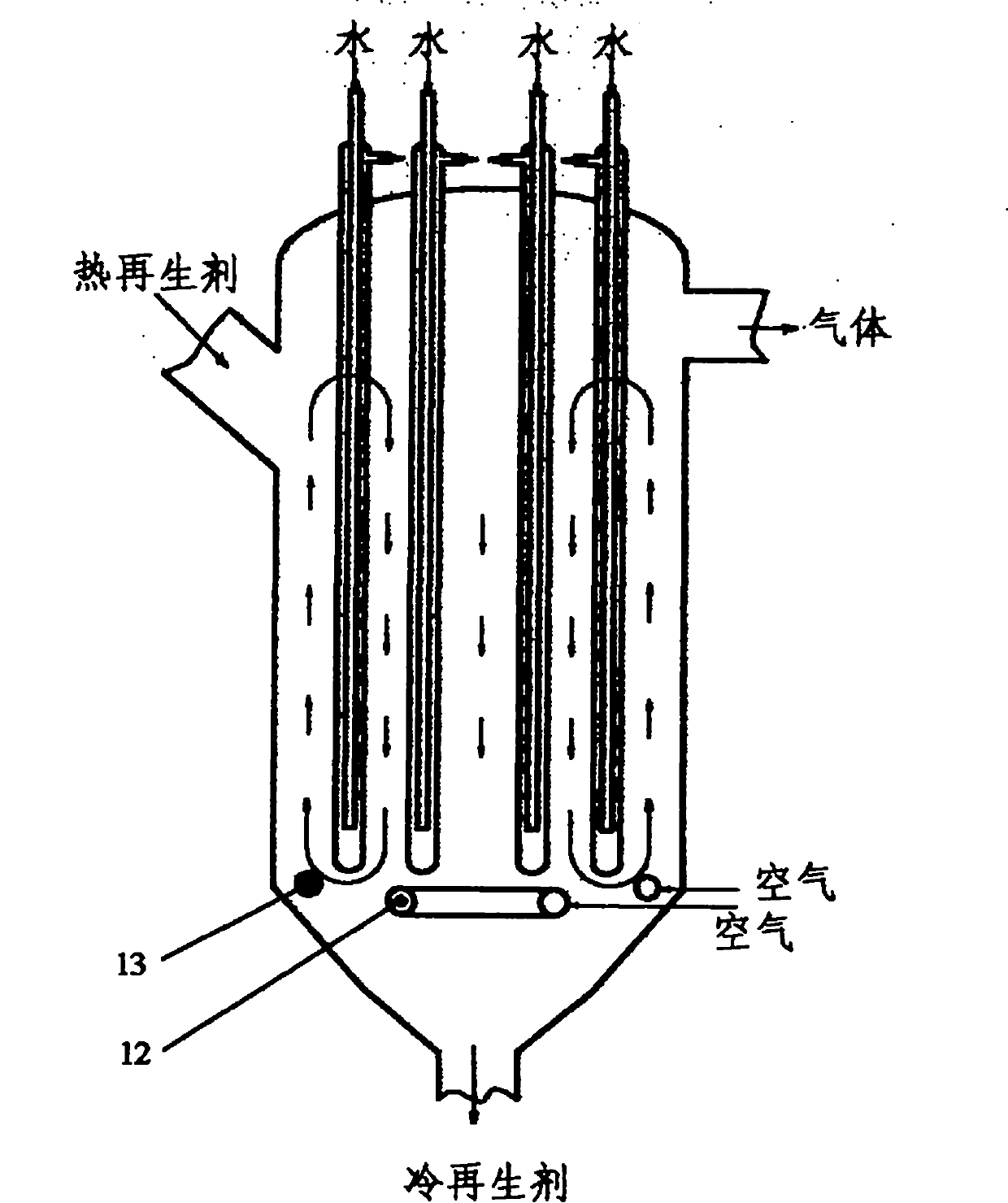
[0043] See figure 2 As shown, this embodiment provides another form of a forced internal mixing type catalytic cracking catalyst external heat extractor 1. In the heat extractor and related operations of this embodiment, the structures and structures not specifically mentioned in the following description The operating conditions are the same as in Example One. The difference from the heat extractor described in Embodiment 1 is that in this embodiment, the central gas distributor 12 arranged at the bottom of the heat extractor 1 and arranged in the axial central area of ​​the heat extractor and arranged on the side wall The peripheral gas distributors 13 of the zone are all annular pipe-type gas distributors, the diameter of the distribution ring of the central gas distributor 12 is (0.4-0.7) D, and the diameter of the distribution ring of the peripheral gas distributor 13 is (0.7-0.95) D, and the two The diameters of the distribution rings are different; the vertical distan...

Embodiment 3

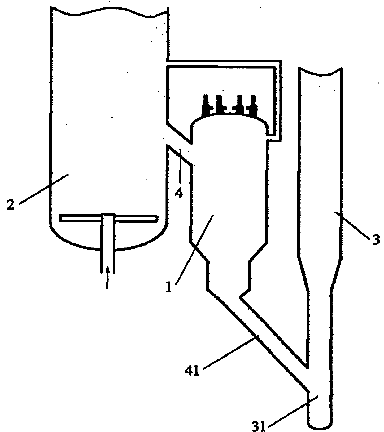
[0045] See image 3 As shown, this embodiment provides a catalytic cracking device using the external heat extractor of the present invention as a catalytic cracking regenerant thermostat and a catalytic cracking method using the device. In the catalytic cracking unit of this embodiment, the regenerant thermostat adopts the heat extractor 1 described in Embodiment 1 or Embodiment 2 of the present invention (it can also be any other form of heat extractor of the present invention), and is arranged in The catalyst regenerator 2 and the catalytic cracking reactor of the catalytic cracking unit are between the riser reactor 3 in the figure, and the catalyst inlet 111 of the heat collector 1 is communicated with the regenerator 2, and the catalyst outlet 113 is communicated with the riser reactor 3 .

[0046] When utilizing this catalytic cracking device to carry out catalytic cracking, the hot regenerant flowing out from the catalyst regenerator 2 first enters in the heat extract...


PUM


Abstract

The invention provides a forced internal recirculation type external cooler for a catalytic cracking catalyst. At least two gas distributors are arranged at the internal bottom of the cooler, and each gas distributor is accessible to fluidized gas independently and can control the gas flow. A plurality of cooling tubes in vertical arrangement are arranged above the gas distributors. Apart from the gas distributors, the cooling tubes and matched fixed parts thereof, no additional components are arranged in the cooler. By controlling the different gas flows of at least two gas distributors, the superficial gas velocity and the bed density in different cross section areas in the cooler are caused to be different and the internal circulation of particles in a bed is strengthened, so the update velocity of the particles on a heat transfer wall is improved and the heat transfer efficiency of the particles and the wall is effectively improved. The cooler has the advantages of simple structure, high heat transfer efficiency and flexible regulation, and can also be used as a themosistor for a catalytic cracking regenerant. In addition, the invention also provides a catalytic cracking device containing the cooler and a catalytic cracking method.

Description

technical field [0001] The invention relates to a catalytic cracking catalyst heat exchange device, in particular to a forced internal mixing type catalytic cracking catalyst external heat extractor, which can also be used as a catalytic cracking regeneration catalyst thermostat, belonging to the petrochemical industry technology field. Background technique [0002] In the petroleum refining industry, catalytic cracking is one of the important secondary processing processes of petroleum. In the catalytic cracking process, heavy macromolecular petroleum hydrocarbons are cracked into small molecular hydrocarbons under high temperature environment and under the catalytic action of molecular sieve catalysts. . In my country, catalytic cracking is the most important means of lightening heavy oil. The vast majority of commercial gasoline and a large part of commercial diesel and chemical raw materials in China come from catalytic cracking. [0003] The catalytic cracking unit is...

Claims


Application Information

Patent Timeline
Patent Type & Authority Applications(China)
IPC IPC(8): F28D13/00F28D1/053B01J8/00
Inventor 卢春喜张永民
Owner CHINA UNIV OF PETROLEUM (BEIJING)
Why Eureka
Try Eureka