Method and device for measuring ground capacitance of DC system
A technology of ground capacitance and DC system, which is applied in the direction of measuring devices, measuring electrical variables, measuring resistance/reactance/impedance, etc., can solve problems such as grounding faults in DC systems, protection malfunctions, system safety hazards, etc., to avoid grounding faults , the effect of preventing impact
- Summary
- Abstract
- Description
- Claims
- Application Information
AI Technical Summary
Problems solved by technology
Method used
Image

Examples
Embodiment 1
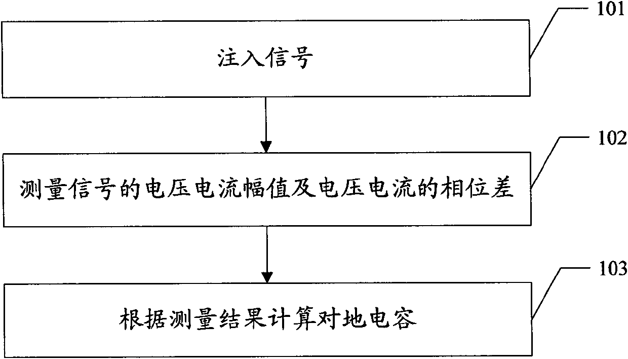
[0033] figure 1 Shown is the schematic flow chart of Embodiment 1 of the method for measuring the ground capacitance of the DC system of the present invention:
[0034] Step 101: Inject the AC signal between the positive and negative bus bars of the DC system and the ground through capacitive coupling;
[0035] Step 102: measuring the voltage amplitude, current amplitude and phase difference of the voltage and current of the AC signal;
[0036] Step 103: Calculate the ground capacitance of the DC system according to formula (3), and calculate the ground insulation resistance of the DC system according to formula (4).
[0037] C + + C - = R 1 2 + X 1 2 2 * π * f ...
Embodiment 2
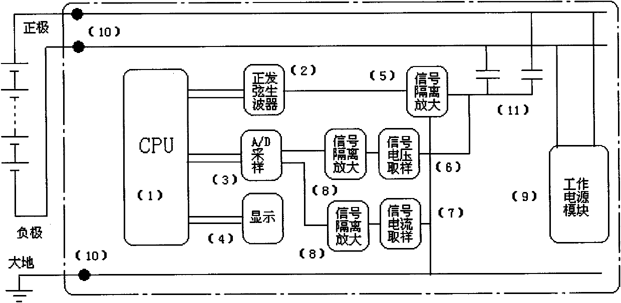
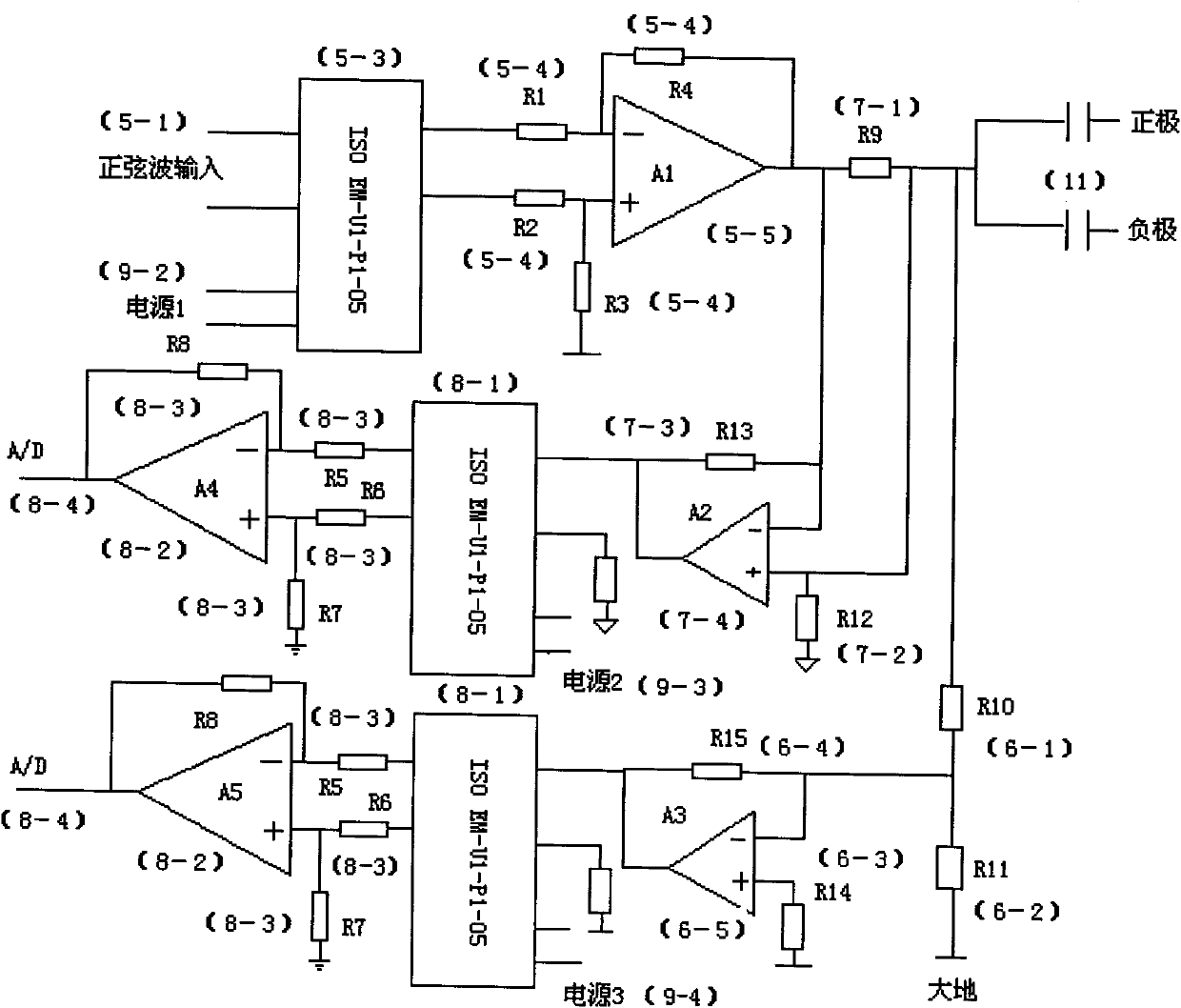
[0044] The difference between this embodiment and Embodiment 1 is that this embodiment adds the steps of signal isolation in Step 101 and Step 102 of Embodiment 1 respectively. In Step 101 of this embodiment, the AC signal is injected through the coupling capacitor after signal isolation. Between the bus bar and the ground, in step 102 of this embodiment, signal isolation processing is performed on the measured voltage amplitude, current amplitude, and voltage-current phase difference of the AC signal.
[0045] Other technical features in the second embodiment are the same as those in the first embodiment, and will not be repeated here.
Embodiment 3
[0047] The difference between this embodiment and Embodiment 2 is that this embodiment adds the steps of signal amplification in Step 101 and Step 102 of Embodiment 2 respectively. In Step 101 of this embodiment, the AC signal is isolated and amplified by the signal and passed through the coupling capacitor Injection between the bus bar and the ground, in step 102 of this embodiment, signal isolation and amplification processing is performed on the measured voltage amplitude, current amplitude, and voltage-current phase difference of the AC signal.
[0048] Other technical features in the third embodiment are the same as those in the second embodiment, and will not be repeated here.
PUM
 Abstract
Description
Claims
Application Information
 - Generate Ideas
- Intellectual Property
- Life Sciences
- Materials
- Tech Scout
- Unparalleled Data Quality
- Higher Quality Content
- 60% Fewer Hallucinations
Browse by: Latest US Patents, China's latest patents, Technical Efficacy Thesaurus, Application Domain, Technology Topic, Popular Technical Reports.
© 2025 PatSnap. All rights reserved.Legal|Privacy policy|Modern Slavery Act Transparency Statement|Sitemap|About US| Contact US: help@patsnap.com