Optical grating displacement sensor distance measuring device based on FPGA
A technology of sensor distance measurement and grating displacement, which is applied in the direction of measuring devices, optical devices, instruments, etc., can solve the problems of unsuitable applications in complex and harsh environments, easy to be interfered by the outside world, and many circuit components, so as to achieve design confidentiality Strong, enhanced anti-interference ability, strong anti-interference ability
- Summary
- Abstract
- Description
- Claims
- Application Information
AI Technical Summary
Problems solved by technology
Method used
Image

Examples
Embodiment Construction
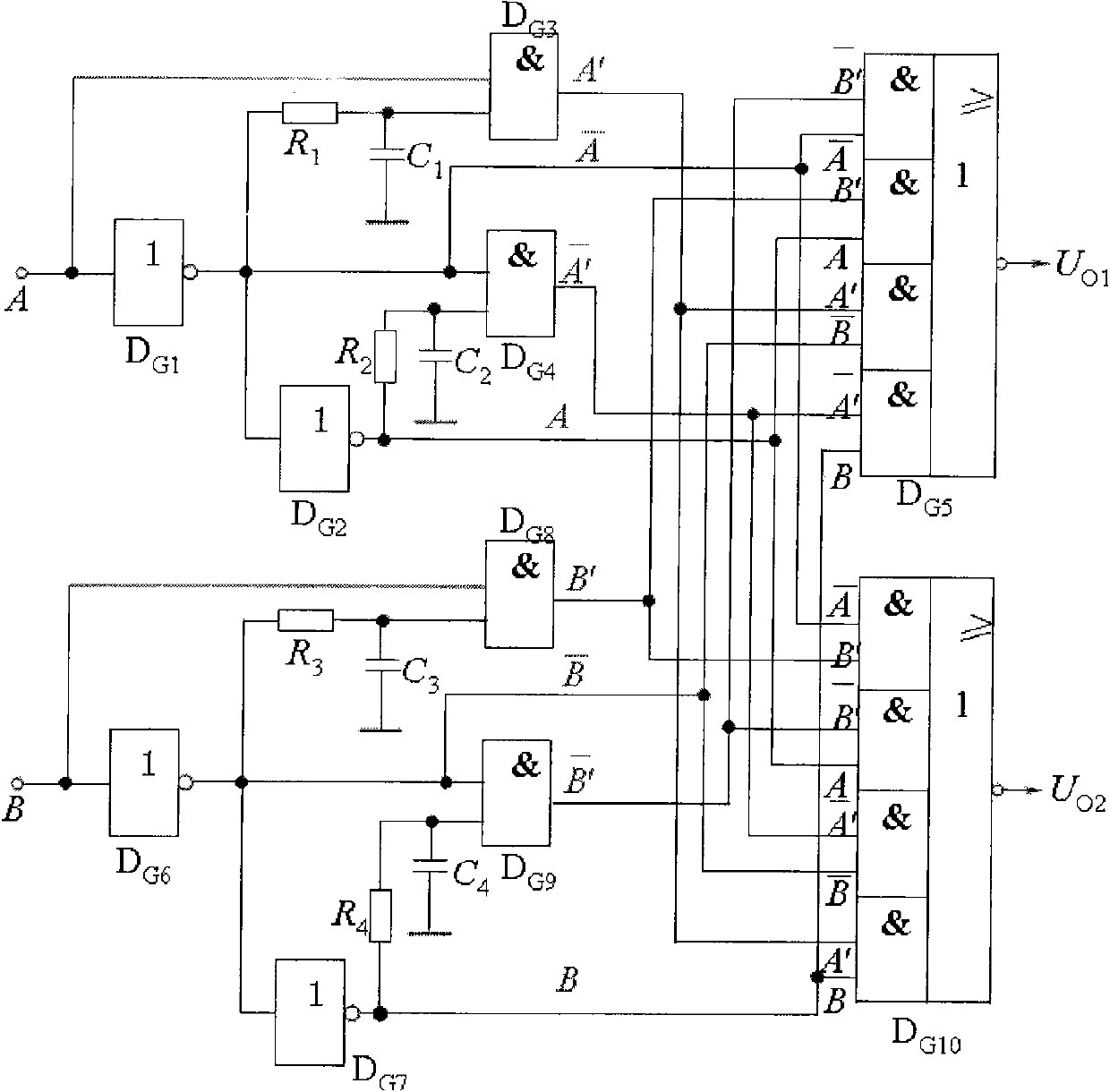
[0009] Such as image 3 As shown, the D flip-flops, NOT gates, AND gates, NOR gates and reversible counters involved in the schematic diagram are programmed and debugged in the VerilogHDL language on the FPGA development software Quartus II provided by Altera.
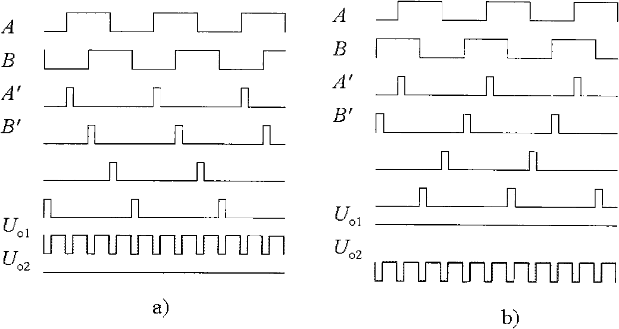
[0010] Such as image 3 As shown, each module compiled and debugged is correctly connected according to the schematic diagram, and it is simulated by the FPGA development software Quartus II, and the output timing is analyzed (such as figure 2 ).
[0011] Customize the Nios II processor as required, and connect the entire system correctly.
[0012] Write the source code for the processor to run, write the entire system wiring and source code into the configuration chip, and perform joint debugging of the system.
[0013] Device model and parameters:
[0014] FPGA chip: Altera's Cyclone II EP2C5Q208C8,
[0015] Parameters: 4608 logic units, embedded 18-bit x18-bit multiplier, dedicated external memory interface ci...
PUM
 Abstract
Description
Claims
Application Information
 - R&D
- Intellectual Property
- Life Sciences
- Materials
- Tech Scout
- Unparalleled Data Quality
- Higher Quality Content
- 60% Fewer Hallucinations
Browse by: Latest US Patents, China's latest patents, Technical Efficacy Thesaurus, Application Domain, Technology Topic, Popular Technical Reports.
© 2025 PatSnap. All rights reserved.Legal|Privacy policy|Modern Slavery Act Transparency Statement|Sitemap|About US| Contact US: help@patsnap.com