Thermoset dampener material
A thermosetting and damping technology, used in polyether coatings, polyacetal coatings, polycarbonate coatings, etc., and can solve problems such as lack of vibration damping materials
- Summary
- Abstract
- Description
- Claims
- Application Information
AI Technical Summary
Problems solved by technology
Method used
Image
Examples
Embodiment A1 and A2
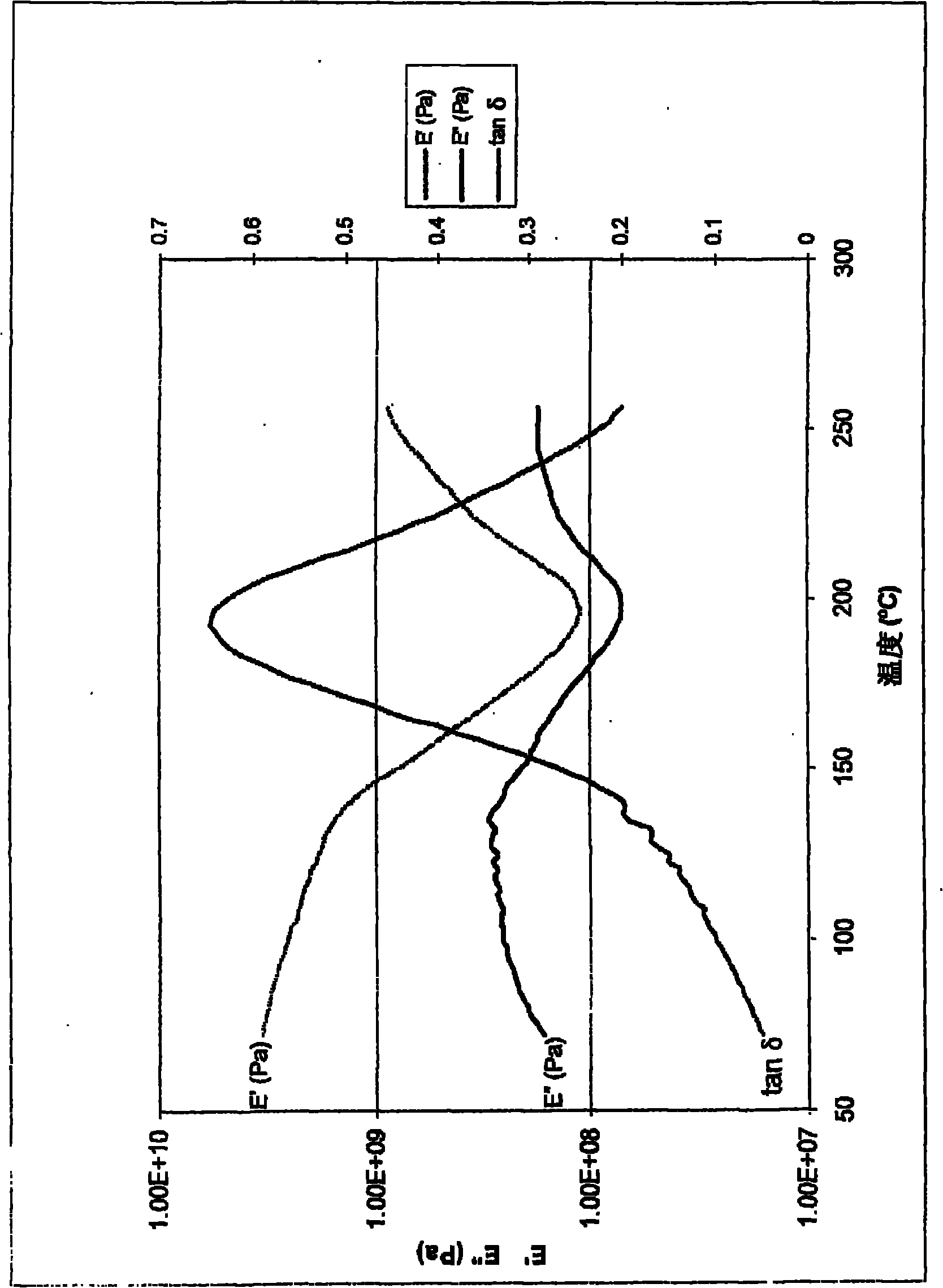
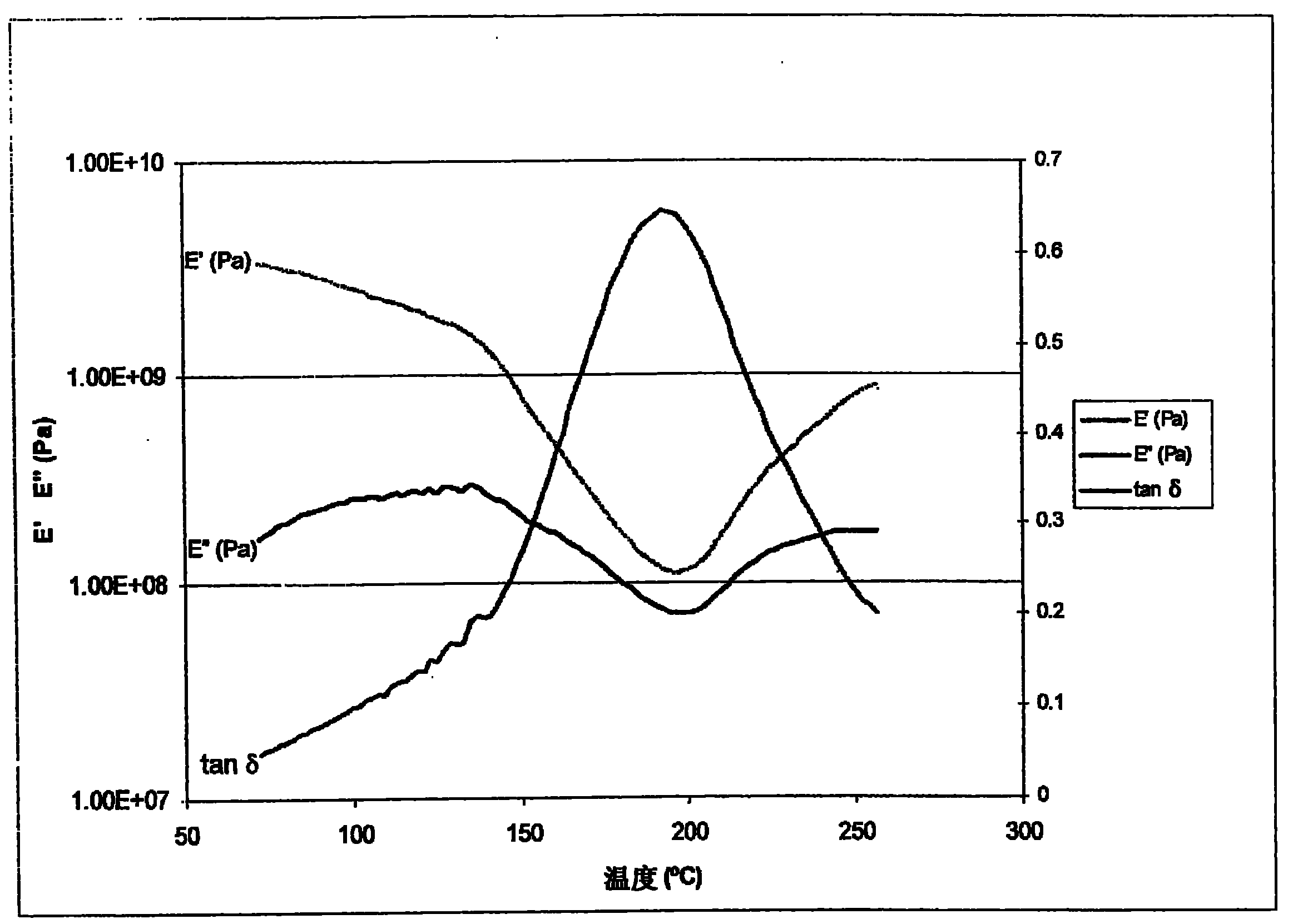
[0126] Examples A1 and A2 were prepared by mixing the resins and hardeners shown in Table 1 in a suitable solvent at ambient temperature. The thermosetting resin PN is a low molecular weight phenol novolak resin, and its phenol equivalent PhEW is 104; the hardener ZE is the oxazole of 5-ethyl-1-aza-3,7-dioxabicyclo[3.3.0]heptane alkyl. For higher viscosity formulations, the formulation is heated to a temperature between 60°C and 80°C to reduce the viscosity of the mixture of components. The mixture was degassed and castings were prepared by pouring the formulation into open molds. The castings were then cured in a ventilated oven at 150°C for 10 minutes, at 180°C for 10 minutes, and at 200°C for 10 minutes. After solidification, the casting was allowed to cool to ambient temperature. The formulations of the cured compositions and properties as measured using dynamic mechanical thermal analysis are provided in Table 1.
[0127] Table 1
[0128] Example
[0129] ...
Embodiment A3 and A4
[0131] Examples A3 and A4 were prepared by mixing the resin, hardener and catalyst as shown in Table 2 in a suitable solvent. Thermosetting epoxy resin E1 is glycidyl ether of bisphenol A, its epoxy equivalent EEW is 180; thermosetting epoxy resin E2 is epoxy novolac resin, its epoxy equivalent EEW is 180; triazine T1 is 2,2- Triazine homopolymer of bis(4-cyanophenyl)propane; bismaleimide B1 is diphenylmethane-4,4'-bismaleimide; catalyst C1 is bis(2-ethane A solution of zinc hexanoate in MEK (methyl ethyl ketone). The formulation is heated to a temperature between 100°C and 120°C to reduce the viscosity of the mixture of components. Castings are prepared by pouring the formulation into open molds. The castings were then cured in a vented oven at 170°C for 60 minutes and at 200°C for 90 minutes. After solidification, the casting was allowed to cool to ambient temperature. The formulations of the cured compositions and properties as measured using dynamic mechanical thermal ...
Embodiment A5
[0136] Example A5 was prepared by mixing resins, hardeners, additives and catalysts as shown in Table 3. Thermosetting epoxy resin E2 is glycidyl ether of bisphenol A, its epoxy equivalent EEW is 187; thermosetting epoxy resin E3 is 3,4-epoxycyclohexylmethyl-3,4-epoxycyclohexanecarboxylic acid Ester, its epoxy equivalent EEW is 135; Hardener H1 is methyl hexahydrophthalic anhydride, its anhydride equivalent AnhEW is 168; Hardener H2 is hexahydrophthalic anhydride, its anhydride equivalent AnhEW is 154; Catalyst C2 is 1-cyanoethyl-2-ethyl-4-methylimidazole; and filler F1 is a crystalline silica filler with a median particle size of about 16 microns. The formulation is heated to a temperature of about 60°C to reduce the viscosity of the mixture of components. The mixture was degassed at 60°C for 15 minutes and castings were prepared by pouring the formulation into open molds. The castings were then cured in a vented oven at 65°C for 95 minutes, at 75°C for 75 minutes, at 115°C...
PUM
| Property | Measurement | Unit |
|---|---|---|
| glass transition temperature | aaaaa | aaaaa |
| length | aaaaa | aaaaa |
| diameter | aaaaa | aaaaa |
Abstract
Description
Claims
Application Information
 - R&D
- Intellectual Property
- Life Sciences
- Materials
- Tech Scout
- Unparalleled Data Quality
- Higher Quality Content
- 60% Fewer Hallucinations
Browse by: Latest US Patents, China's latest patents, Technical Efficacy Thesaurus, Application Domain, Technology Topic, Popular Technical Reports.
© 2025 PatSnap. All rights reserved.Legal|Privacy policy|Modern Slavery Act Transparency Statement|Sitemap|About US| Contact US: help@patsnap.com


