Transparent electrode

Inactive Publication Date: 2011-07-14
KOLON IND INC
View PDF5 Cites 7 Cited by
  • Summary
  • Abstract
  • Description
  • Claims
  • Application Information

AI Technical Summary

Benefits of technology

[0021]Since the transparent electrode according to the present invention includes a polyimide film, serving as a substrate, satisfying an average linear thermal expansion coefficient and having a yellowness of 15 or less and an electrode layer formed by dispersing a conductive material in a polyimide resin satisfying an average linear thermal expansion coefficient and having a yellowness of 15 or less, the transparent electrode of the present invention is advantageous in that a problem of a short circuit does not occur even when apparatuses including this transparent electrode are over-heated because it has excellent heat resistance, and in that it is transparent and has high electroconductivity.
[0022]Hereinafter, preferred embodiments of the present invention will be described in detail.
[0023]A transparent electrode according to an embodiment of the present invention includes a polyimide film, serving as a substrate, having an average linear thermal expansion coefficient of 50.0 ppm/° C. or less, which is measured by thermo-mechanical analysis based on a film thickness of 50˜100 μm at a temperature of 50˜250° C., and a yellowness of 15 or less. When the average linear thermal expansion coefficient of the polyimide film is more than 50.0 ppm/° C., the difference in thermal expansion coefficient between the polyimide film and a plastic substrate is increased, so that there is a problem in that a short circuit occurs when apparatuses provided with the transparent electrode are over-heated or when their temperature is high. Further, when the yellowness of the polyimide film is more than 15, the transparency of the transparent electrode decreases, so that it is not preferable that the polyimide film be used to manufacture the transparent electrode. In this case, the average linear thermal expansion coefficient of the polyimide film is obtained by measuring the change in length of the polyimide film depending on the increase of temperature at a predetermined temperature range, a

Problems solved by technology

However, the indium tin oxide (ITO) is problematic in that high process costs are required because a vacuum process is needed to form an ITO thin film and in that the lifespan of a flexible display becomes short because the ITO thin film easily breaks when the flexible display is bent or folded.
However,

Method used


Image

  • Transparent electrode
  • Transparent electrode
  • Transparent electrode

Examples


preparation example 1

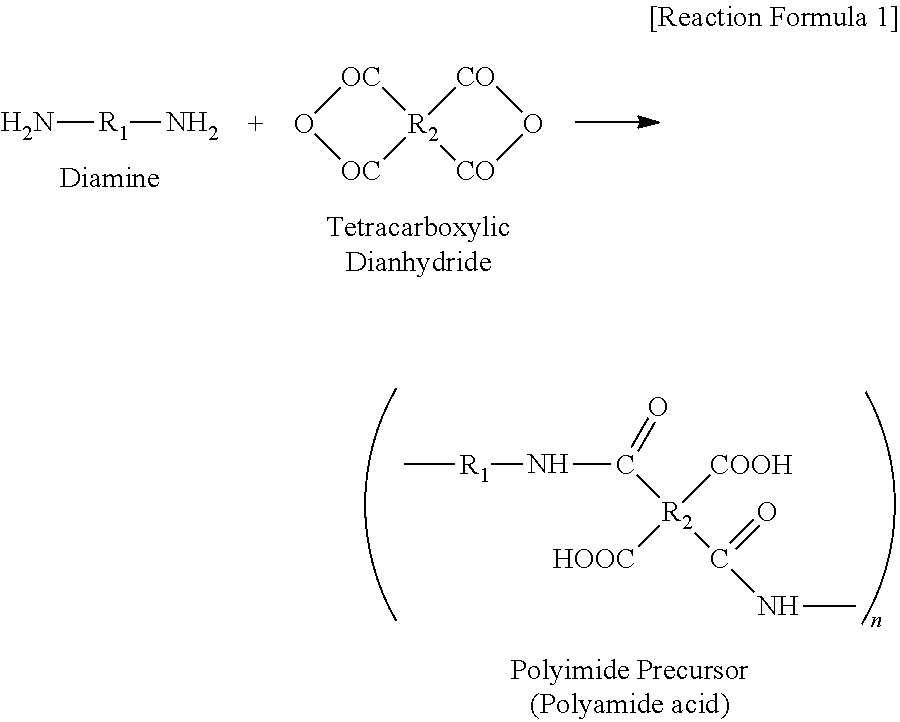
[0046]A polyimide precursor solution (solid content: 20%) was prepared by polycondensing 2,2′-bis(trifluoromethyl)-4,4′-diaminobiphenyl (2,2′-TFDB) and biphenyltetracarboxylic dianhydride (BPDA) with 2,2-bis(3,4-dicarboxyphenyl)hexafluoropropane dianhydride (6-FDA) in dimethylacetamide using a commonly-used method. This reaction procedure is represented by Reaction Formula 1 below.

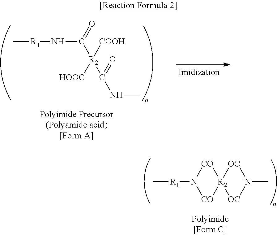
[0047]Subsequently, 2˜4 equivalents of acetic anhydride (Samjeon Chemical Co., Ltd.) and pyridine (Samjeon Chemical Co., Ltd.), serving as curing agents, were respectively added to 300 g of the polyimide precursor solution to form a polyamic acid solution. Then, the polyamic acid solution was heated at a heating rate of 1˜10° C. / min for 2˜10 hours to a temperature of 20˜180° C. to partially imidize (partially cure) the polyamic acid solution, thereby preparing a solution containing a partially-imidized (partially-cured) intermediate.

[0048]The following Reaction Formula 2 represents a reaction procedure use...

preparation example 2

[0057]34.1904 g of N,N-dimethylacetamide (DMAc) was charged in a 100 mL 3-neck round-bottom flask, as a reactor, provided with a stirrer, a nitrogen injector, a dropping funnel, a temperature controller and a cooler while passing nitrogen through the flask, and then the reactor is cooled to 0° C., and then 4.1051 g (0.01 mol) of 6-HMDA was dissolved in the N,N-dimethylacetamide (DMAc) to form a first solution, and then the first solution was maintained at 0° C. Subsequently, 4.4425 g (0.01 mol) of 6-FDA was added to the first solution to form a second solution, and then the second solution was stirred for 1 hour to completely dissolve 6-FDA in the second solution. In this case, the concentration of solid matter in the second solution was 20 wt %. Thereafter, this second solution was stirred for 8 hours at room temperature to obtain a polyamic acid solution having a viscosity of 2400 cps at 23° C.

[0058]After the reaction was completed, the obtained polyamic acid solution was applied ...

preparation example 3

[0059]Similar to in Preparation Example 2, 2.87357 g (0.007 mol) of 6-HMDA was dissolved in 32.2438 g of N,N-dimethylacetamide (DMAc) to form a first solution, and then 0.7449 g (0.003 mol) of 4-DDS was added to the first solution and then completely dissolved therein to form a second solution. Subsequently, 4.4425 g (0.01 mol) of 6-FDA was added to the second solution to form a third solution, and then the third solution was stirred for 1 hour to completely dissolve 6-FDA in the third solution. In this case, the concentration of solid matter in the third solution was 20 wt %. Thereafter, this third solution was stirred for 8 hours at room temperature to obtain a polyamic acid solution having a viscosity of 2300 cps at 23° C.

[0060]Thereafter, a polyimide film was prepared using the same method as in Preparation Example 2.


PUM


Abstract

Disclosed herein is a transparent electrode, including: a polyimide film having an average linear thermal expansion coefficient of 50.0 ppm/° C. or less, which is measured by thermo-mechanical analysis based on a film thickness of 50˜100 μm at a temperature of 50˜250° C., and a yellowness of 15 or less; and an electrode layer including a conductive material and a polyimide resin having an average linear thermal expansion coefficient of 50.0 ppm/° C. or less, which is measured by thermo-mechanical analysis based on a film thickness of 50˜100 μm at a temperature of 50˜250° C., and a yellowness of 15 or less. The transparent electrode is advantageous in that a problem of a short circuit does not occur even when apparatuses including this transparent electrode are over-heated because it has excellent heat resistance, and in that it is transparent and has high electroconductivity.

Description

TECHNICAL FIELD[0001]The present invention relates to a transparent electrode, and, more particularly, to a transparent electrode in which an organic electrode layer is formed on a plastic film.BACKGROUND ART[0002]As computers, electrical household appliances and communication appliances are digitalized and their performance is rapidly increased, it is keenly required to realize large-size portable displays. Display materials which can be folded and rolled like a newspaper are required in order to realize portable large-area flexible displays.[0003]Therefore, electrode materials for displays not only must be transparent and exhibit low resistance but also must exhibit high strength such that devices can be mechanically stabilized even when they are bent or folded. Further, electrode materials for displays must have a thermal expansion coefficient similar to that of a plastic substrate such that appliances are not short-circuited or their surface resistance is not greatly changed eve...

Claims


Application Information

Patent Timeline
IPC IPC(8): B32B7/02B82Y99/00
CPCH01B1/20H01B1/24Y10T428/24975H01L51/5206H05B33/28H01J2211/225H10K50/81H10K2101/00H01B1/16H05B33/10G02F1/1335H01J11/22
Inventor JUNG, HAK GEEKIM, JEONG HANPARK, HYO JUNSONG, SANG MIN
Owner KOLON IND INC
Why Eureka
Try Eureka