Device for removing laser paint and application method thereof

An application method and laser technology, applied in laser welding equipment, welding equipment, metal processing equipment, etc., can solve the problems of decline in defective products, environmental pollution, and high labor costs

Inactive Publication Date: 2010-07-14
WUHAN LINGYUN PHOTOELECTRONICS SYST
View PDF0 Cites 37 Cited by
  • Summary
  • Abstract
  • Description
  • Claims
  • Application Information

AI Technical Summary

Problems solved by technology

[0008] The first method, due to the huge daily output of electronic components, sometimes 100,000 per day, requires a lot of personnel to operate, such as scraping off about 2000 pins of electronic components for 10 hours a day per person, then Only 50 people are needed. If the output expands, it is necessary to continuously recruit people to meet the demand.
Moreover, manual scraping has inconsistencies in the scraped surface, easy damage to the electronic component body, injury to feet, broken feet, etc., resulting in a high rate of defective produ...

Method used


Image

  • Device for removing laser paint and application method thereof
  • Device for removing laser paint and application method thereof
  • Device for removing laser paint and application method thereof

Examples


example 1

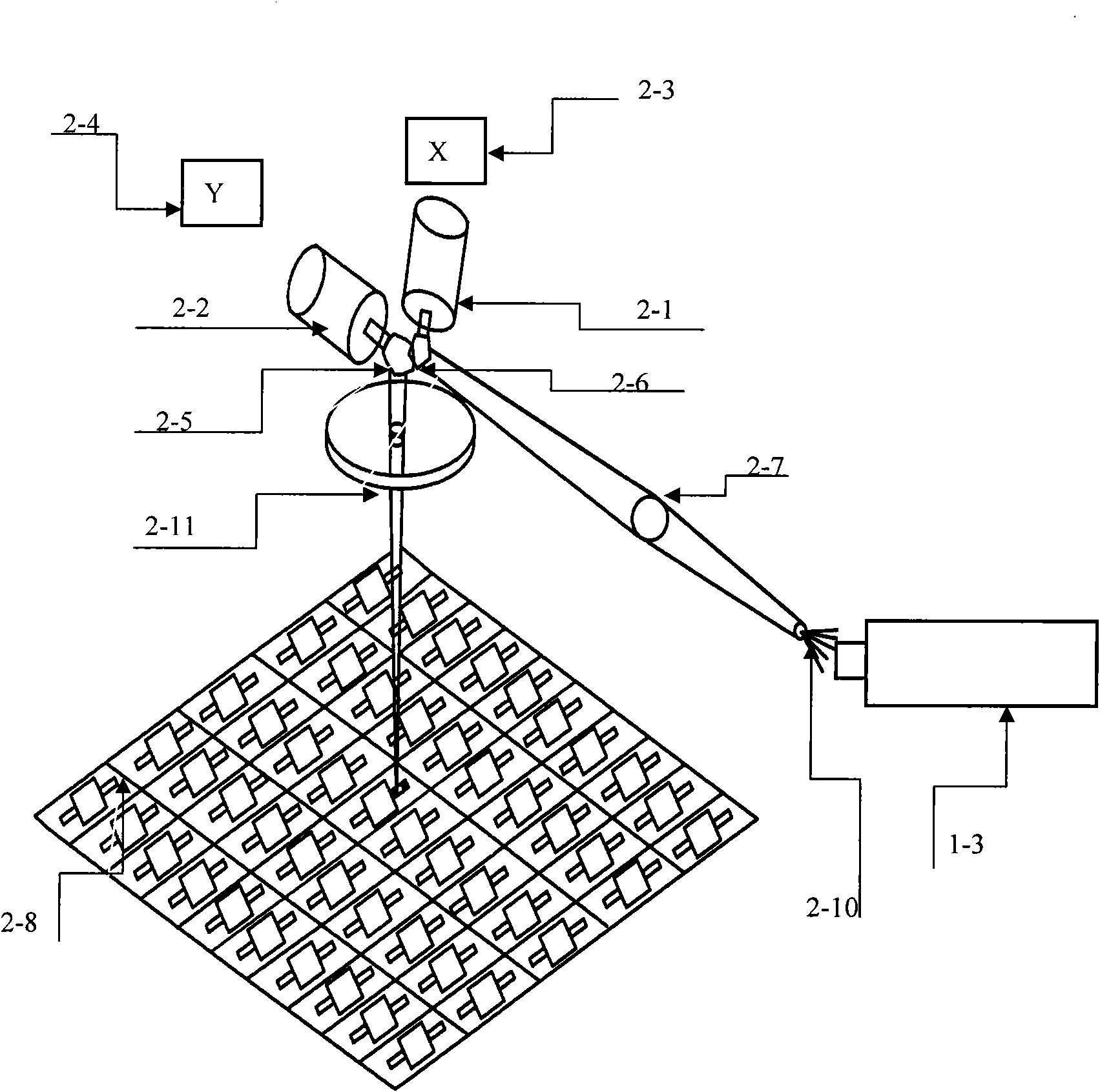
[0047] Example 1, in the embodiment, the laser paint removal operation is performed on the semi-finished solid-state inductors 2-8 of the 06 series. Since the pins of this inductor only have insulating varnish and no black paint, a green laser generator is used to complete the laser removal. paint job.

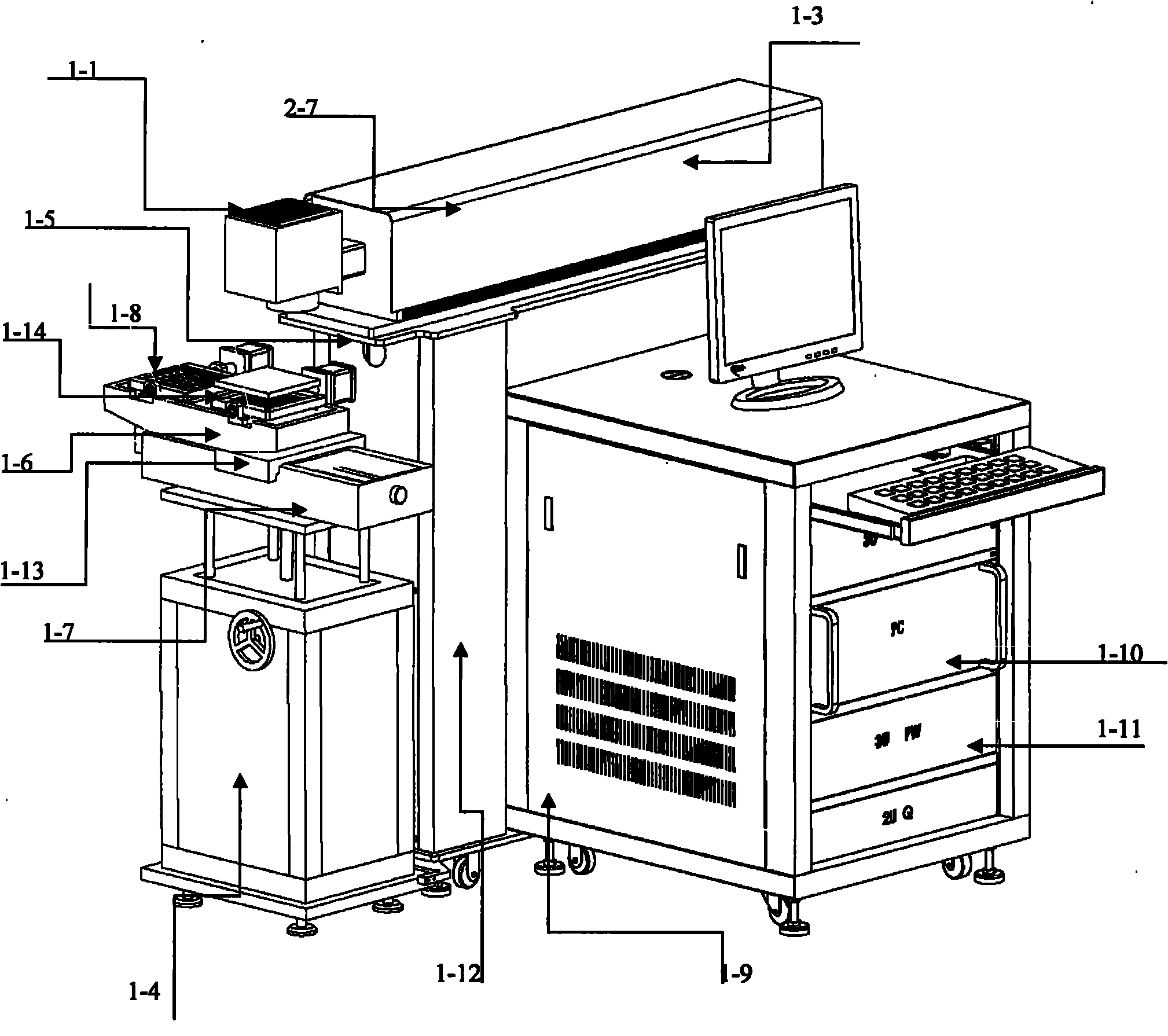
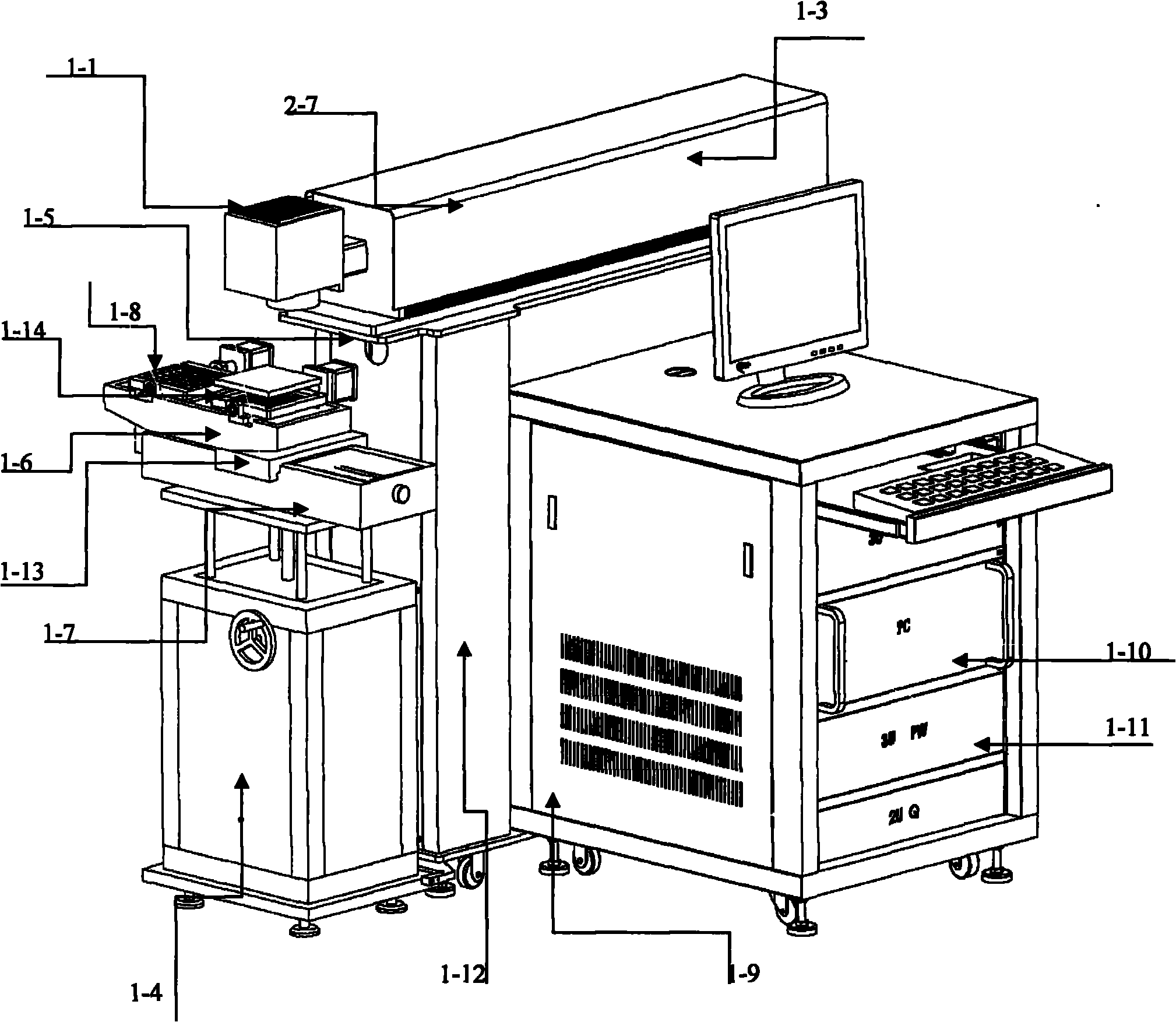
[0048] First place the solid inductors 2-8 on the fixture tray 1-8 one by one. For the 06 series tray, each tray can hold 80 inductors. After placing the device fixture tray 1-8 on the station turning platform 1-6 In the card slot of the flip frame, it needs to be placed at two stations at the same time at the beginning. When the start button is turned on, the motion platform 1-7 will move slowly under the drive of the controller 1-9, that is, the servo motor controlled by PLC. When the position is 1, the motion platform 1-7 stops. We use the In-Sight 5400 series vision sensor from COGNEX as an independent vision system to deploy in this application environment, and cooperate ...

example 2

[0049] Example 2, in the embodiment, the laser paint removal operation is performed on semi-finished solid-state inductors 2-8 with specifications of 10 (10mm*10mm) series. Since the pins of this inductor have both insulating varnish and black varnish, red laser Generator to complete the laser paint removal work.

[0050] First place the solid inductors 2-8 on the fixture trays 1-8 one by one. For 10 series trays, 40 inductors can be placed on each tray. After placing them, place the device fixture trays 1-8 on the station turning platform 1-6. In the card slot of the flip frame, it needs to be placed at two stations at the same time at the beginning. When the start button is turned on, the translation platform moves slowly under the drive of the servo mechanism controlled by PLC1-9. When it reaches the position of work 1, the movement platform 1-7 stops, we use the In-Sight 5400 series vision sensor from COGNEX as an independent vision system to deploy in this application env...


PUM


Abstract

The invention relates to a device for removing laser paint and an application method thereof. The device comprises a laser generator, a supporting platform seat, a moving platform, an overturning mechanism, an automatic camera positioning system, an industrial control computer, a laser power supply and a two-dimensional galvanometer scanning system. The invention is characterized in that the moving platform is provided with a station overturning mechanism, and the side surface of the moving platform is provided with the automatic camera positioning system; a cross beam of the supporting platform seat is provided with an X-Y axis galvanometer scanning unit and a laser generator; and the industrial control computer is respectively connected with the laser generator, the X-Y axis galvanometer scanning unit and an overturning platform controller (PLC) by cables. The invention has compact structure, automatic and accurate positioning, high working efficiency and the like, and can be widely applied in the fields of removing the paint of a semi-finished product of a solid electronic component. The invention relates to the application method for removing laser paint, which adopts an overturning and position-switching mechanism to realize the removing of a paint layer of pins of the electronic component.

Description

technical field [0001] The invention relates to a paint removal device and method, in particular to a laser paint removal device and application method. Background technique [0002] At present, in the field of discrete electronic components, electronic components have gradually developed towards miniaturization of volume and solid-state packaging. That is, the volume is smaller, and the packaging is also developing towards a packaging method similar to integrated block ICs. [0003] In the new process manufacturing process, the surface paint layer must be removed from the pins of discrete electronic components (such as inductors), so as to facilitate the implementation of the subsequent soldering process. [0004] In the previous process, due to the requirements of the process, the overall paint spraying operation must be carried out, plus the insulating varnish on the enameled wire itself, so that two layers of paint will be formed on the pins of the electronic components...

Claims


Application Information

Patent Timeline
IPC IPC(8): B23K26/40B23K26/04B23K26/08
Inventor 王锋吴华吕超宋平
Owner WUHAN LINGYUN PHOTOELECTRONICS SYST
Why Eureka
Try Eureka