Mixed polishing method suitable for air valves

A valve and polishing device technology, applied in the field of chemical polishing, can solve the problems of micro-cracks on the valve surface, large dust pollution, dullness and the like

Active Publication Date: 2010-07-14
HUAI JI DENG YUE VALVE CO LTD
View PDF0 Cites 5 Cited by
  • Summary
  • Abstract
  • Description
  • Claims
  • Application Information

AI Technical Summary

Problems solved by technology

The traditional method is to use shot blasting to remove the thermal oxide layer, and its disadvantage is that the dust pollution is large, and the surface of the valve is prone to micro-cracks, which are not bright
The traditional valve polishing equipment uses a shot blasting machine to directly spray iron shot onto the surface of the valve through a spray gun under the action of compressed air, so that the surface of the valve after treatment is prone to micro-cracks and is not bright

Method used


Image

  • Mixed polishing method suitable for air valves
  • Mixed polishing method suitable for air valves
  • Mixed polishing method suitable for air valves

Examples


Embodiment Construction

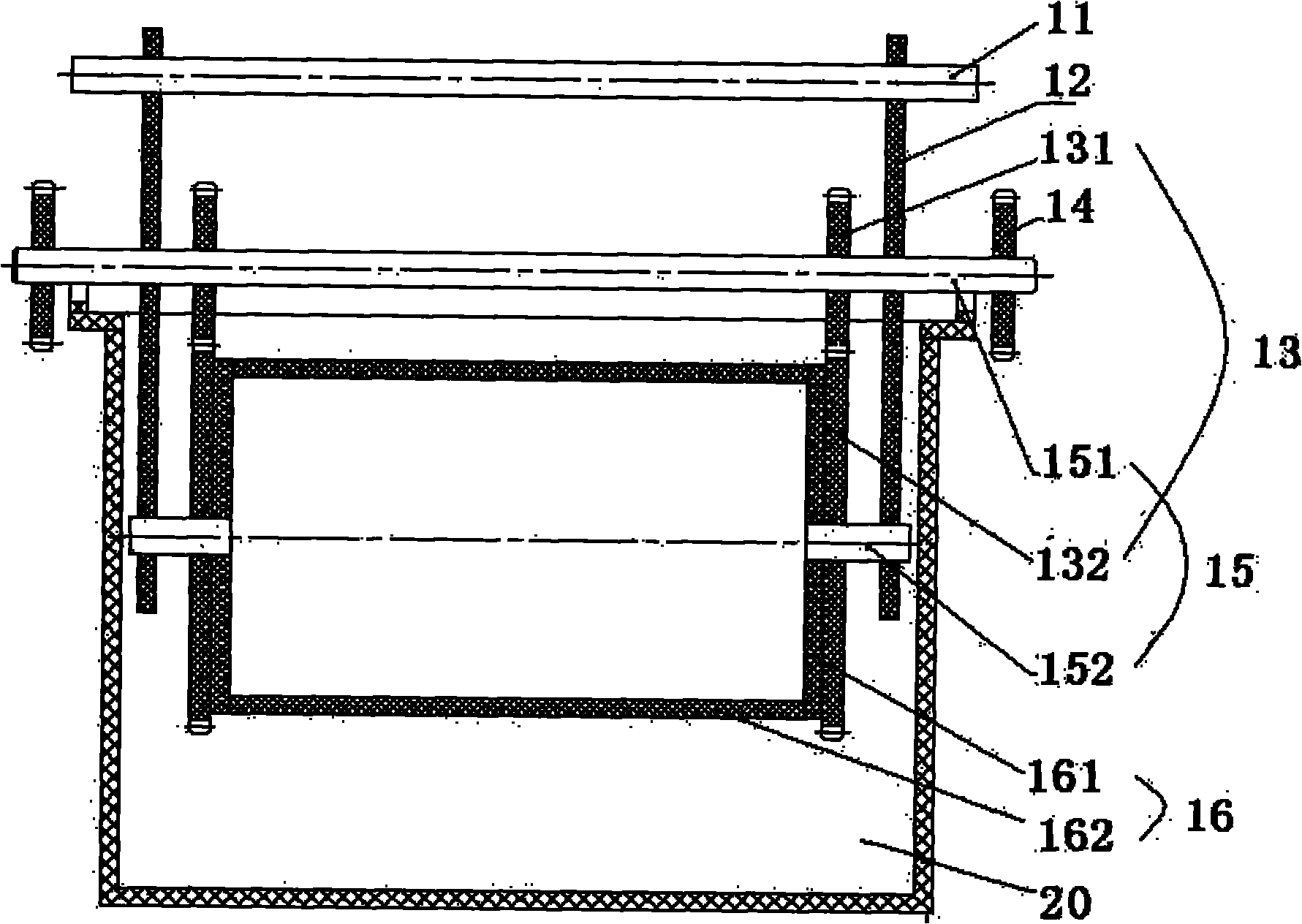
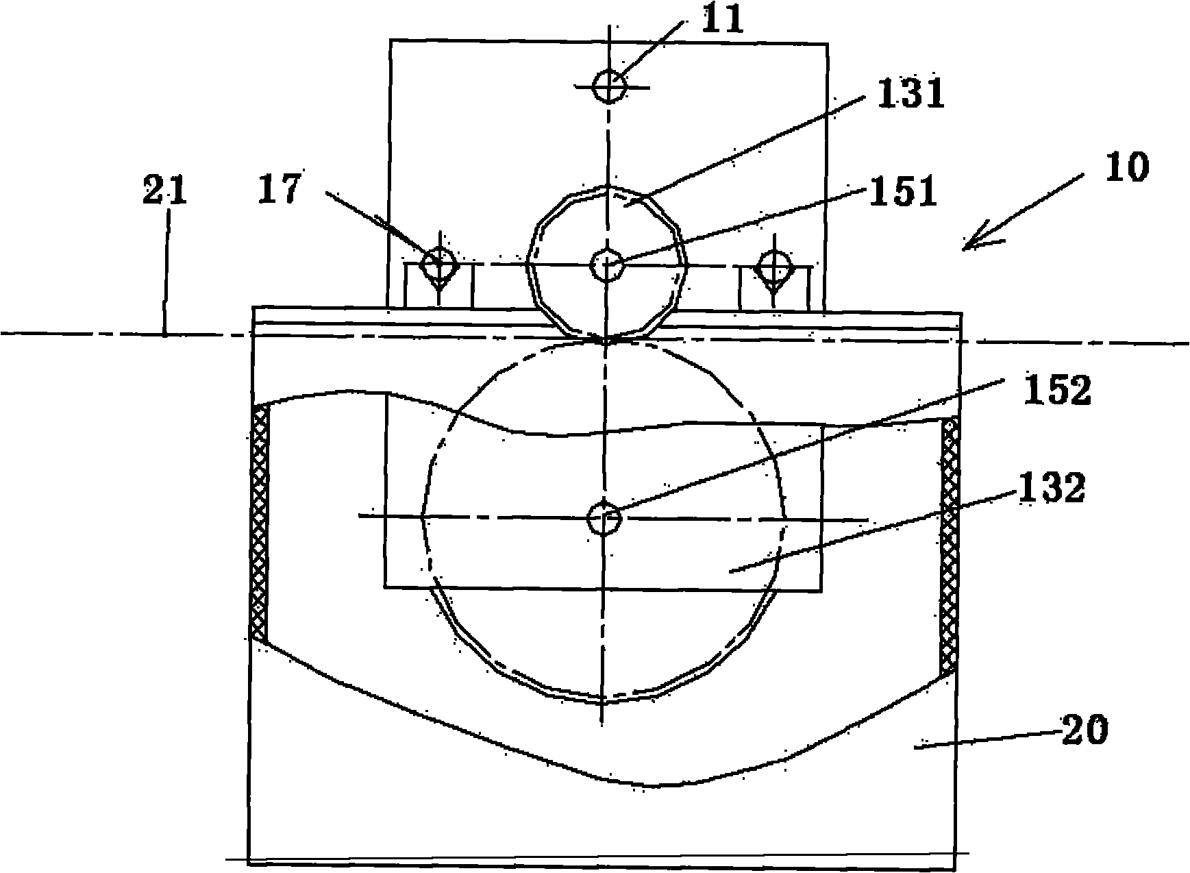
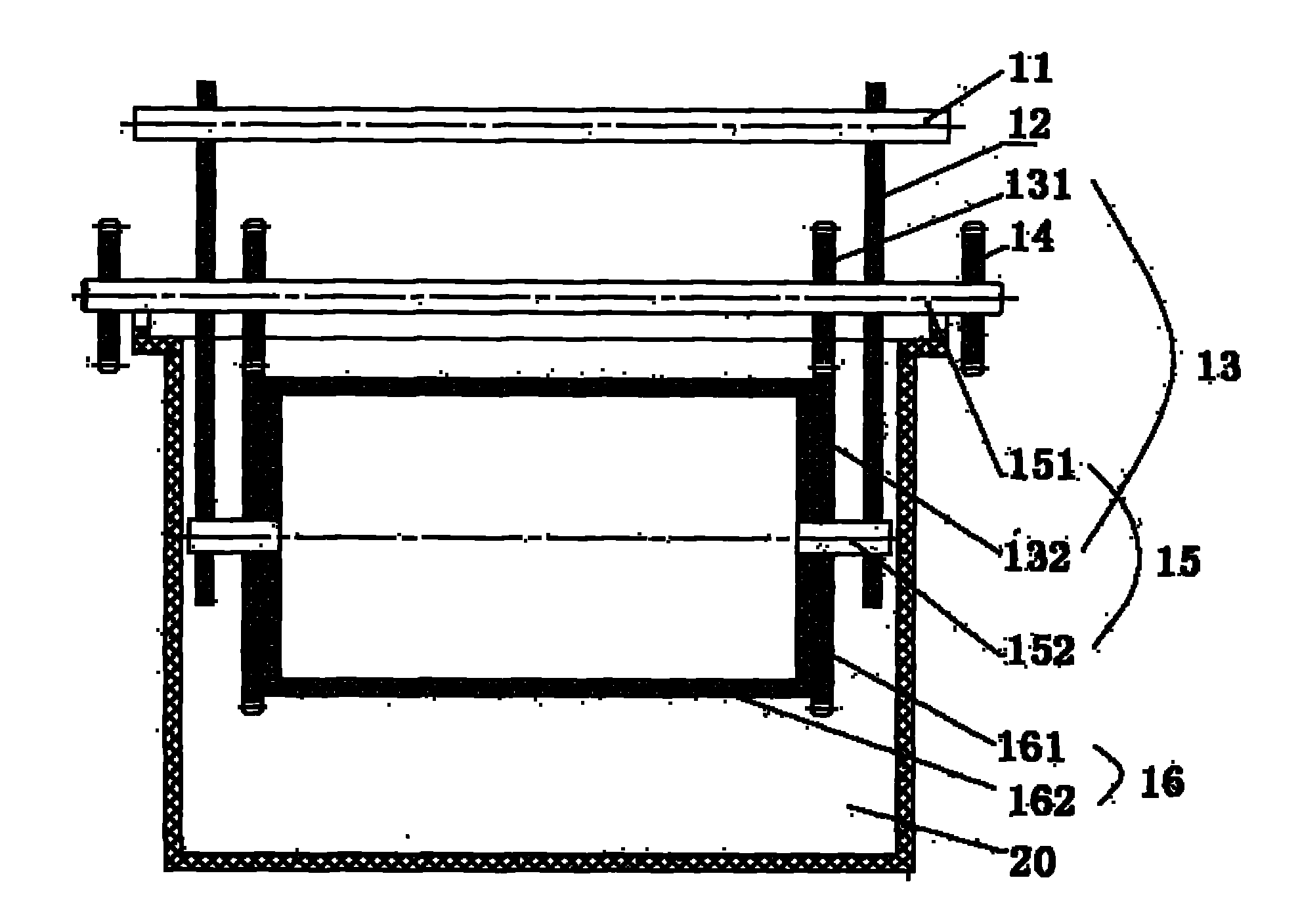
[0025] see figure 1 with 2 as shown, figure 1 Shown is the Valve Hybrid Polisher, figure 2 for figure 1 left view of . The valve mixing and polishing device of the present invention is composed of a drum assembly 10 and a polishing tank 20 .

[0026] Wherein, the drum assembly 10 is composed of the suspension rod 11, the fixed plate 12, the gear assembly 13 (the first gear 131, the second gear 132), the sprocket 14, the connecting shaft 15 (the first connecting shaft 151, the second connecting shaft 152) , flat drum plate 16, circular drum plate 17, and support shaft 18; the material of boom 11 and support shaft 18 is 1Cr18Ni9 sprocket 14, and the material of sprocket 14 is No. 45 steel; the fixed plate 12, the first gear 131, the first The material of the connecting shaft 151, the second gear 132, the second connecting shaft 152, the flat roller plate 16, and the round roller plate 17 is PVC.

[0027] The cylinder 16 is welded by 2 identical flat cylinder plates 161, 1...


PUM

PropertyMeasurementUnit
Diameteraaaaaaaaaa

Abstract

The invention relates to a polishing technology, in particular to a mixed polishing method and a device thereof suitable for air valves. In the mixed polishing method of the invention, an air valve after heat treatment is loaded into a rotary drum, and after chemical acid dipping and alkali neutralization, abrasive particles are loaded in, thereby realizing chemical and mechanical mixed polishing of the air valve through the rotation of the rotary drum in a chemical treatment solution. The invention can effectively remove an oxide layer after heat treatment of the air valve, and realize polishing of the non-mechanically processed surface of the air valve on the premise of no generation of microcracks.

Description

technical field [0001] The invention relates to a polishing process, which belongs to the technical field of chemical polishing, in particular to a hybrid polishing method and device for valves. Background technique [0002] The valve is a key part of the engine, and thermal oxidation layers and microcracks are not allowed to appear on its surface. The manufacture of the valve must undergo heat treatment. After heat treatment, a thermal oxide layer will appear on the surface of the valve, and some surfaces of the valve after heat treatment will no longer be machined. The traditional method is to use shot peening to remove the thermal oxide layer, and its disadvantages are that the dust pollution is large, and the surface of the valve is prone to micro-cracks, which are not bright. The traditional valve polishing equipment uses a shot blasting machine, which directly sprays iron shot onto the valve surface through a spray gun under the action of compressed air, so that the t...

Claims


Application Information

Patent Timeline
IPC IPC(8): B24B31/02
Inventor 莫东强卢杰初邓炜明罗华欢傅文兰罗建东宁志坚孔伟王飞华孔祥刚郑小原邹天熬袁添华李德植才燕
Owner HUAI JI DENG YUE VALVE CO LTD
Why Eureka
Try Eureka