Active shock absorber for oil drilling

An active shock absorption, oilfield drilling technology, applied in drilling equipment, drill pipes, drill pipes, etc., can solve the problems of unstable working performance, spring fatigue failure, major engineering risks, etc., and achieve stable and reliable working performance, stability and reliability. Good sealing, good shock absorption effect

Active Publication Date: 2010-07-14
金锋
View PDF6 Cites 11 Cited by
  • Summary
  • Abstract
  • Description
  • Claims
  • Application Information

AI Technical Summary

Problems solved by technology

Spring damping is easy to cause spring fatigue failure, and the final load is still added to the drill collar
Such as the Chinese patent CN2767638Y published on March 29, 2006 discloses a kind of such shock absorber, which is easy to cause the fatigue failure of the spring
The hydraulic passive damping device has relatively high requirements on the sealing performance of its own piston. Under high underground confining pressure (deep well), the piston has to overcome the confining pressure to work, which greatly increases the piston sealing load, causing hydraulic oil to leak easily. After leakage, the shock absorption function will be lost, the working performance will be unstable, and due to the impact of internal piston without damping expansion and contraction, it will cause a major safety hazard for drilling tools
If the shock absorber that has lost its shock absorbing function is replaced midway, it is necessary to lift tens or hundreds of tons of drilling tools from the bottom of the well, which will seriously affect the work efficiency and increase the drilling cost.
Therefore, the downhole safety factor of this kind of shock absorbing tool with expansion and contraction compensation on the length of the drilling tool is low, and there is a great engineering risk

Method used


Image

  • Active shock absorber for oil drilling
  • Active shock absorber for oil drilling

Examples


Embodiment Construction

[0015] Below in conjunction with accompanying drawing, the present invention is further described:

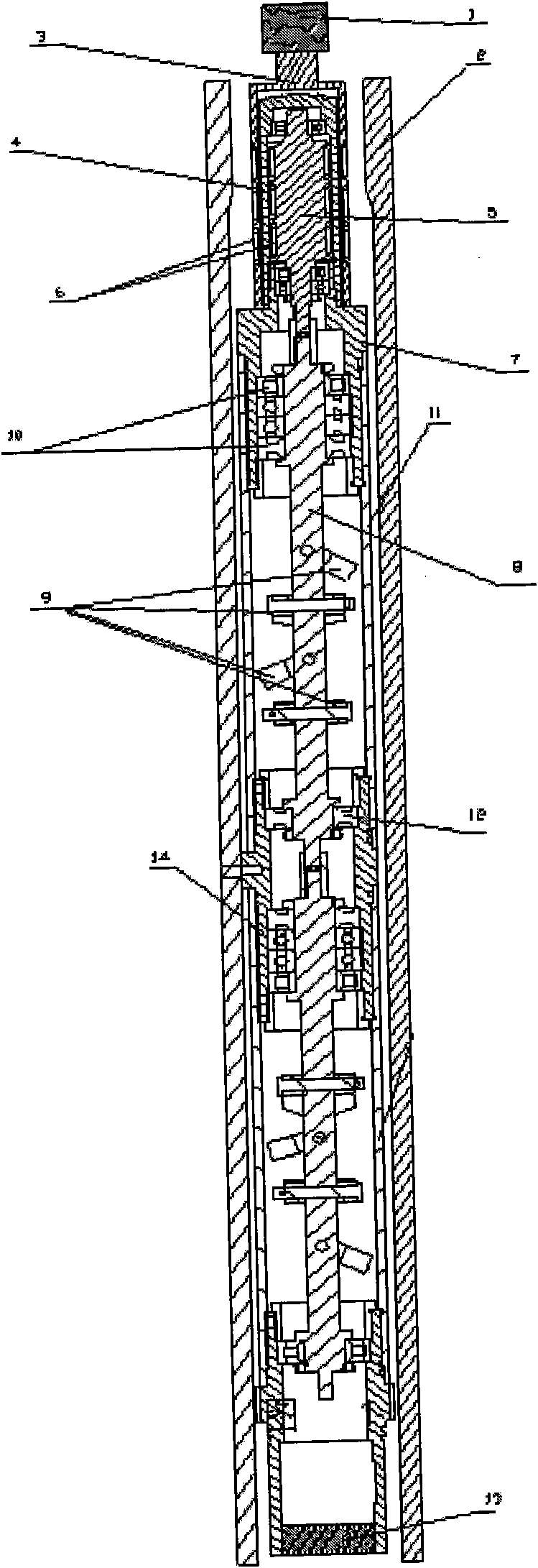
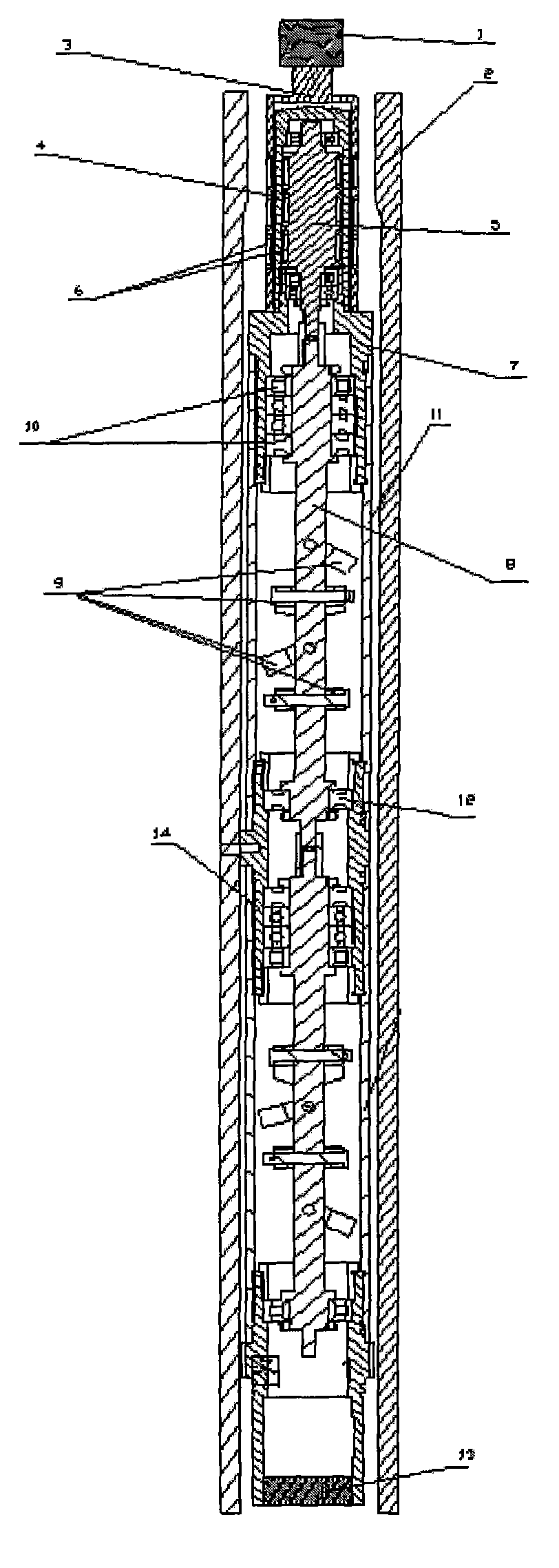
[0016] see figure 1 , a shock absorber for oil field drilling, the shock absorber is fixedly installed in the drill collar 2, such as fixed in the drill collar 2 by bolts. The shock absorber includes a power source 1, a magnetic coupling mechanism and a shock absorber. The power source 1 is, for example, a motor, a turbine or the like. The magnetic coupling mechanism is connected with the power source 1. The magnetic coupling mechanism includes an outer magnetic barrel 3, a coupling shaft 5, and an isolation sleeve 4. The coupling shaft 5 is placed in the outer magnetic barrel 3, and between the outer magnetic barrel 3 and the coupling shaft 5 A spacer 4 is provided, and a plurality of heteropolar magnet blocks 6 are fixedly installed on the outer wall of the outer magnetic barrel 3 and the coupling shaft 5 respectively. When the power source 1 drives the outer magnetic cyli...


PUM


Abstract

The invention relates to an active shock absorber for oil drilling. The active shock absorber, which is fixed in a drill collar, comprises a power source, a magnetic coupling mechanism and a shock-absorbing joint; the upper end of the magnetic coupling mechanism is connected with the power source, and the lower end of the magnetic coupling mechanism is connected with the shock-absorbing joint; the shock-absorbing joint comprises a shock-absorbing shaft and an even number of semi-annular metal balance weights hinged with the shock-absorbing shaft and axially arranged on the shock-absorbing shaft at intervals; the magnetic coupling mechanism transfers the rotational motion of the power source to the shock-absorbing shaft in order to drive the balance weights to rotate; and under the effect of self inertia and centripetal force, the balance weights generate an acceleration opposite from the direction of shock. The active shock absorber can actively absorb shock, and depends on the gyroscopic effect of rotating the rotor swing block, that is, the shock absorber can generate resistance enough to resist the shock load generated by a generating source within the range of ability, the working performance is stable and reliable, and the shock-absorbing effect is good.

Description

Technical field: [0001] The invention belongs to a shock absorber in the field of oil field drilling, in particular to an active shock absorber for oil field drilling. Background technique: [0002] The shock absorber eliminates the damage to the drilling rod string caused by the drill bit jump by absorbing the drill bit bounce energy and converting it into other forms of energy. Drill tool damage can cause engineering accidents and seriously cost the oil well. The current downhole damping device is generally a telescopic damping damper that compensates the length of the drilling tool, such as a spring-type passive damper, or a hydraulic passive damper. The spring damping is easy to cause spring fatigue failure, and the final load is still added to the drill collar. For example, the Chinese patent CN2767638Y disclosed on March 29, 2006 discloses a kind of such shock absorber, which is easy to cause the fatigue failure of the spring. The hydraulic passive damping device has...

Claims


Application Information

Patent Timeline
Patent Type & Authority Applications(China)
IPC IPC(8): E21B17/07
Inventor 金锋
Owner 金锋
Why Eureka
Try Eureka