Oil pumping machine

A technology of pumping unit and sucker rod, which is applied in the direction of using electric mode for temperature control, production of fluid, drilling equipment, etc., can solve the problems of low mechanical efficiency, difficult pumping unit, large process energy consumption, etc. Control and network control, reduction of reactive power loss, highly targeted effect

Active Publication Date: 2010-07-14
SHIJIAZHUANG TONGAN MACHINERY CO LTD
View PDF0 Cites 7 Cited by
  • Summary
  • Abstract
  • Description
  • Claims
  • Application Information

AI Technical Summary

Problems solved by technology

[0004]①Low mechanical efficiency: the reciprocating motion is realized from the rotation of the motor shaft to the oil cylinder, which is realized by belt deceleration, gear deceleration, four-bar linkage, etc., and the process consumes a lot of energy , the mechanical transmission efficiency is very low
[0005]②Easy to wear and short service life: In order to realize the movement of the oil rod, the beam pumping unit needs a large driving torque. faster, resulting in a shorter service li

Method used


Image

  • Oil pumping machine
  • Oil pumping machine
  • Oil pumping machine

Examples


Embodiment 1

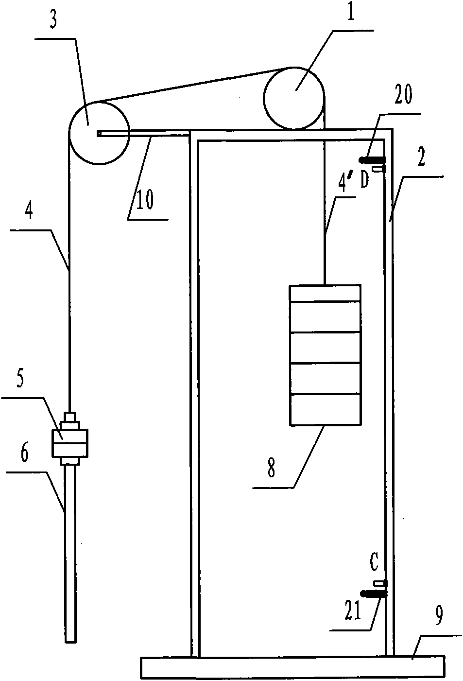
[0060] figure 1 Shown is a pumping unit, which includes a fixed drive host 1 , a tower 2 fixed on a foundation 9 , and a first sucker rod 6 driven by the drive host 1 .

[0061] The driving host 1 is a permanent magnet synchronous reducer, and it is an upper-mounted type relative to the tower 2: that is, the driving host 1 is fixed on the top and middle of the tower 2, and the combined counterweight 8 is located in the tower 2 and is set at the lower part of the driving host 1 and is biased to the outside. The top edge of the opposite side of the side where the counterweight 8 is located on the tower 2 is fixed with a guide wheel support 10 extending outwards, and the axle of the wire rope guide wheel 3 is fixedly hinged on the guide wheel support 10; The host 1 is provided with a wire rope reel driven by the output shaft of the drive host 1, and two wire ropes 4 and 4' are wound on the wire rope reel, one end of which is respectively fixed on the wire rope drum, and their fre...

Embodiment 2

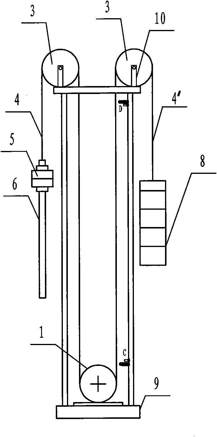
[0096] The difference between the present embodiment and the first embodiment is only that the distribution of the driving host 1 and the tower 2 is different, and the structure of other parts is the same as that of the first embodiment.

[0097] In this embodiment, the drive host 1 is a lower-mounted type relative to the tower 2, refer to figure 2 The driving host 1 is fixed on the foundation 9 below the tower frame 2; the two side edges corresponding to the top of the tower frame 2 corresponding to the top of the driving host 1 are respectively fixed with guide wheel brackets 10, and the axles of the wire rope guide wheels 3 are fixed and hinged to the guide on the wheel bracket 10; two wire ropes 4 and 4' are wound on the wire rope reel, one end of which is respectively fixed on the wire rope reel, and their free ends are fixed and hinged to the wire rope guide wheel 3 on the tower through the wheel axle. The first sucker rod 6 and the combined counterweight 8 are connecte...

Embodiment 3

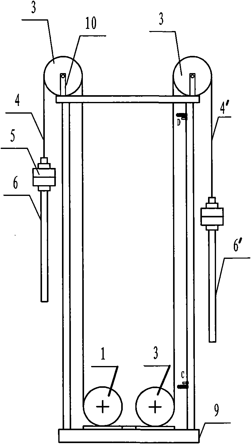
[0099] The difference between this embodiment and the second embodiment is only that the distribution of the drive host 1 and the tower 2 is different, and the structure of other parts is the same as that of the first embodiment.

[0100] In this embodiment, the drive host 1 is a lower-mounted type relative to the tower 2, refer to image 3 : the driving host 1 is fixed on the foundation 9 below the tower frame 2, and the foundation 9 is also provided with a wire rope guide wheel arranged in parallel with the driving host 1; the combined counterweight 8 and the second sucker rod 6 in the first embodiment 'Replacement; at the top of the tower 2 corresponding to the two side edges of the top of the drive main frame 1, guide wheel brackets 10 are respectively fixed, and the axle of the wire rope guide wheel 3 is fixedly hinged on the guide wheel bracket 10; on the wire rope reel, there are two Steel wire ropes 4 and 4′, one end of which is respectively fixed on the wire rope reel...


PUM


Abstract

The invention discloses an oil pumping machine which comprises a fixedly arranged driving host of a permanent magnet synchronous speed reducer, a pylon fixed on a foundation and a first oil pumping rod driven by the driving host, wherein a steel wire cable drum which is driven by an output shaft of the driving host and wound with two steel wire cables is arranged on the driving host; one end of one steel wire cable is fixed on the drum, while the other end is fixed and articulated to a guide wheel on the pylon through a wheel shaft and then connected with the first oil pumping rod; one end of the other steel wire cable is fixed on the drum, while the other end passes through the guide wheel and then is connected with a counterweight or directly connected with the counterweight without passing through the guide wheel; and the wheel shaft of the guide wheel and the axis of the steel cable drum are horizontally arranged in parallel. The invention has reduced energy consumption, simple structure and convenient maintenance, can conveniently adjust the stroke and the jig frequency of an oil well, has the functions of diagnosing and detecting the working state of the oil well at any time and can further realize digital control and remote network control. The oil pumping machine is used as a petroleum exploitation machine.

Description

technical field [0001] The invention belongs to oil mining machinery, in particular to an oil pumping unit. Background technique [0002] At present, the pumping units commonly used in oil mining machinery are beam pumping units and vertical pumping units, etc., which are composed of an electric motor, a belt reduction device, a gear reducer, and a four-bar linkage mechanism. The pin shaft on the support reciprocates, drives the donkey head to move up and down, and makes the oil rod drive the oil well pump to move up and down to achieve the purpose of oil pumping. [0003] The pumping unit of above-mentioned structure has following shortcoming: [0004] ①Low mechanical efficiency: The reciprocating motion from the rotation of the motor shaft to the oil cylinder is realized through belt deceleration, gear deceleration, four-bar linkage, etc. The process consumes a lot of energy and the mechanical transmission efficiency is very low. [0005] ②Easy to wear and short service ...

Claims


Application Information

Patent Timeline
IPC IPC(8): E21B43/00E21B19/084G05D23/19
Inventor 刘鸿坤孙向荣李拓新
Owner SHIJIAZHUANG TONGAN MACHINERY CO LTD
Why Eureka
Try Eureka