Interface unit containing capillary electrophoresis of hollow-fiber membrane and chemoluminescence combination

A technology of capillary electrophoresis and chemiluminescence, which is applied in the fields of chemiluminescence/bioluminescence, measuring devices, and analysis by making materials react chemically, and can solve the problem of limiting the application range of chemiluminescence capillary electrophoresis detectors and the mixing of luminescent reagents and analytes Insufficient uniformity and stability, capillary electrophoresis cut-off and other problems, to achieve separation analysis, improve column efficiency and detection sensitivity, and eliminate dead volume

Inactive Publication Date: 2010-07-21
EAST CHINA UNIV OF SCI & TECH
View PDF4 Cites 2 Cited by
  • Summary
  • Abstract
  • Description
  • Claims
  • Application Information

AI Technical Summary

Problems solved by technology

For the sleeve-type interface, experiments have proved that this interface technology has many advantages, but there are also some obvious deficiencies: ①Because there are gaps in the interface, it is easy to introduce air bubbles to cut off the capillary electrophoresis, and the detection cannot be carried out; ②When the analyte is separated from the electrophoresis When the tube flows out into a reaction tube with a larger inner diameter and mixed with the luminescent reagent, it is easy to cause eddy current diffusion, resulting in peak broadening and lower column efficiency; ③The mixing of luminescent reagent and analyte is not uniform and stable, which affects the reproducibility; ④Luminescent reagent The flow rate needs to match the flow rate of the analyte in the separation tube. If the flow rate of the luminescent reagent is too high, the detected optical signal will be incomplete, which will affect the peak height or peak area. Otherwise, it will be caused by staying in the detection window for too long. Peak broadening; these problems limit the range of applications of chemiluminescence as a capillary electrophoresis detector

Method used


Image

  • Interface unit containing capillary electrophoresis of hollow-fiber membrane and chemoluminescence combination
  • Interface unit containing capillary electrophoresis of hollow-fiber membrane and chemoluminescence combination
  • Interface unit containing capillary electrophoresis of hollow-fiber membrane and chemoluminescence combination

Examples


Embodiment 1

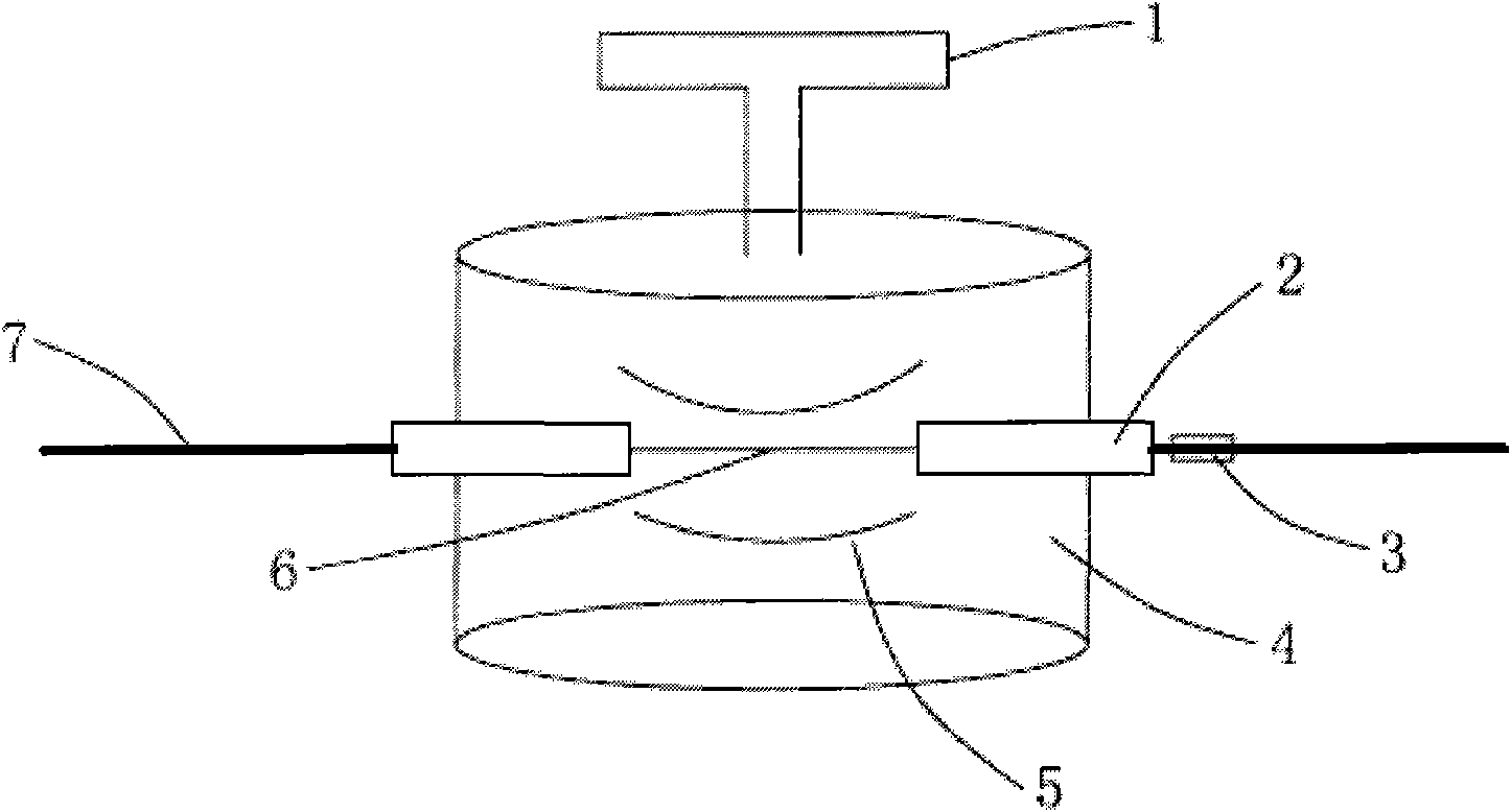
[0027] Please see attached figure 1 , an interface device for combined use of capillary electrophoresis and chemiluminescence containing a hollow fiber membrane. Take a hollow fiber membrane 6 with a length of about 10-15 mm, insert its two ends into a Teflon tube 2 with a length of 5-10 mm, and expose it to the tube. The hollow fiber membrane 6 of the outer part is about 3 to 5 mm long, and the edge of the connection between the Teflon tube 2 and the hollow fiber membrane 6 is tightly sealed with epoxy resin; hole, and the above-mentioned connected hollow fiber membrane 6 passes through the holes on both sides of the plastic box 4, and is installed in the plastic box 4, and the pores on both sides of the plastic box 4 are sealed with epoxy resin; the plastic box 4 contains chemical For the luminescent reagent 5, in order to speed up the penetration of the chemiluminescent reagent 5 in the hollow fiber membrane 6, a pressure-driven device 1 is added on the top of the plastic b...

Embodiment 2

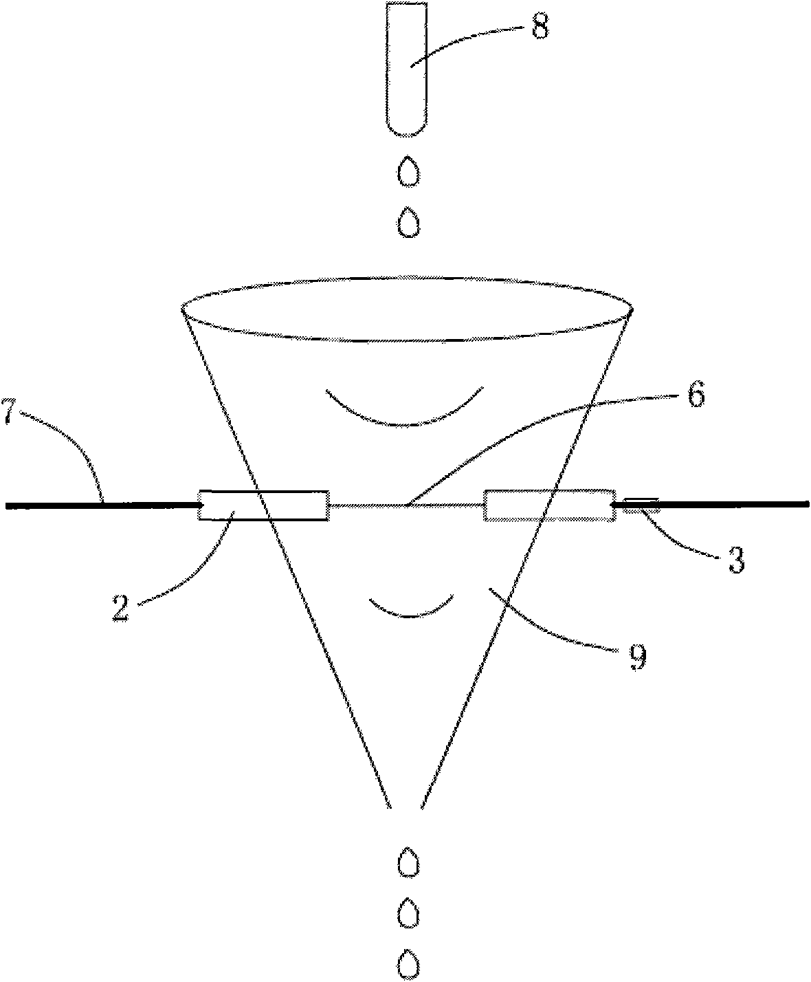
[0030] Please see attached figure 2, an interface device for combined use of capillary electrophoresis and chemiluminescence containing a hollow fiber membrane. Take a hollow fiber membrane 6 with a length of about 10-15 mm, insert its two ends into a Teflon tube 2 with a length of 5-10 mm, and expose it to the tube. The hollow fiber membrane 6 of the outer part is about 3-5mm long, and the edge connecting the Teflon tube 2 and the hollow fiber membrane 6 is tightly sealed with epoxy resin. Get a pipette tip 9, punch two holes equivalent to the outer diameter of the Teflon tube 2 on both sides, pass the above-mentioned connected hollow fiber membrane 6 through the holes on both sides of the pipette tip 9, and install it on the In the pipette tip 9, the pores on both sides are sealed with epoxy resin; Add the chemiluminescent reagent 5 dropwise with the dropper 8 to the top of the pipette 8, and the bottom flows out, that is, the chemiluminescent reagent 5 is flowing in the p...

Embodiment 3

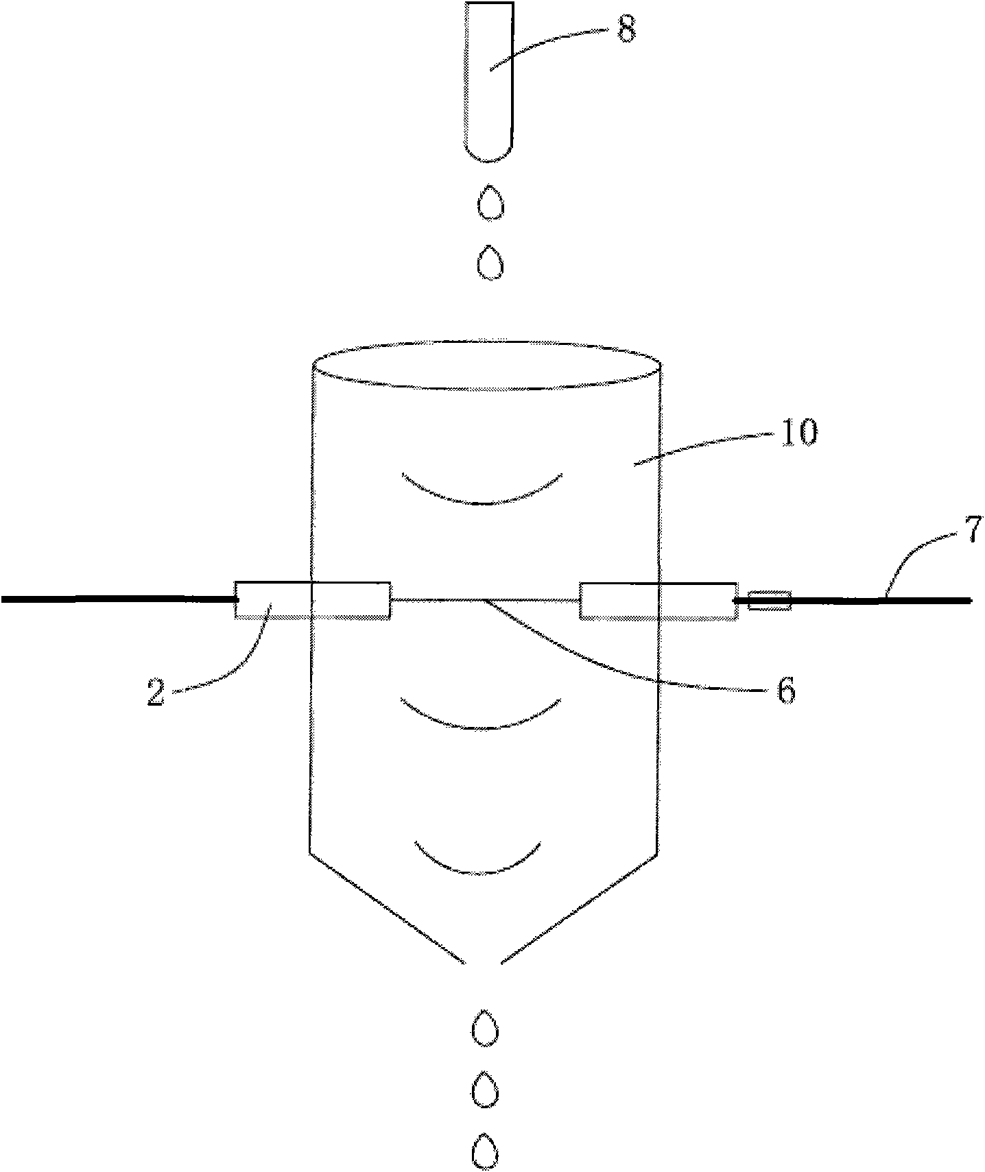
[0033] Please see attached image 3 , an interface device for combined capillary electrophoresis and chemiluminescence containing a hollow fiber membrane. Take a hollow fiber membrane 6 with a length of 10-15 mm, insert its two ends into a Teflon tube 2 with a length of 5-10 mm, and expose it to the outside of the tube. Part of the hollow fiber membrane 6 is about 3 to 5 mm long, and the edge of the connection between the Teflon tube 2 and the hollow fiber membrane 6 is tightly sealed with epoxy resin; Teflon tube 2 has a suitable hole in the external diameter, and the above-mentioned connected hollow fiber membrane 6 is passed through the holes on both sides of the centrifuge tube 10, and is installed in the centrifuge tube 10, and the pores on both sides are sealed with epoxy resin; the centrifuge tube 10 Built-in chemiluminescent reagent 5, in order to speed up the penetration of chemiluminescent reagent 5 in the hollow fiber membrane 6, so drop the chemiluminescent reagent...


PUM


Abstract

The invention relates to an interface unit containing capillary electrophoresis of a hollow-fiber membrane and chemoluminescence combination, which at least comprises a hollow-fiber membrane. The hollow-fiber membrane is arranged between an injection port of a capillary and a detection window, both ends of the hollow-fiber membrane are respectively inserted into a Teflon tube, and the edges for connecting the Teflon tube with the hollow-fiber membrane are bonded and sealed by epoxide resin; chemiluminescence reagent is mixed with a sample through the hollow-fiber membrane, the chemiluminescence reaction is carried out, and a chemiluminescence detector is used for further detection. The interface unit has the advantages of high column efficiency and detection sensitivity, simple structure,convenient operation, easy control and wide application range.

Description

【Technical field】 [0001] The invention relates to the technical field of capillary electrophoresis, in particular to an interface device for combined use of capillary electrophoresis and chemiluminescence containing a hollow fiber membrane. 【Background technique】 [0002] Capillary electrophoresis (CE), a new separation technique developed in the 1980s, has become one of the most active research directions in analytical chemistry. While capillary electrophoresis has the advantages of high efficiency, rapidity, less sample volume and less reagent consumption, it is also restricted by the difficulty of micro-sample detection. Solving the problem of capillary electrophoresis micro-sample detection is one of the key technologies for the further development of this method. . Combined with the highly sensitive and convenient chemiluminescence detection technology, the application range of capillary electrophoresis can be broadened to a certain extent. The combination of capillar...

Claims


Application Information

Patent Timeline
Patent Type & Authority Applications(China)
IPC IPC(8): G01N21/01G01N21/76
Inventor 刘海燕韩宁杜一平张维冰
Owner EAST CHINA UNIV OF SCI & TECH
Why Eureka
Try Eureka