Robot remote control welding system and method used for remote welding

A remote welding and robot technology, applied in welding equipment, auxiliary welding equipment, welding/cutting auxiliary equipment, etc., can solve the problems of high real-time requirements, poor visual feedback of remote welding, poor adaptability of remote welding, etc., to reduce Work load, high real-time requirements, and good adaptability

Inactive Publication Date: 2010-08-04
HARBIN INST OF TECH
View PDF0 Cites 48 Cited by
  • Summary
  • Abstract
  • Description
  • Claims
  • Application Information

AI Technical Summary

Problems solved by technology

[0004] The purpose of the present invention is to solve the problems of high real-time requirements of the welding process in the current remote control welding, poor adaptability of remote cont

Method used


Image

  • Robot remote control welding system and method used for remote welding
  • Robot remote control welding system and method used for remote welding
  • Robot remote control welding system and method used for remote welding

Examples


specific Embodiment approach 1

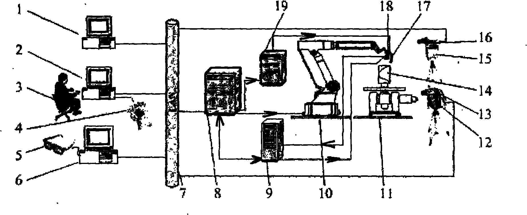
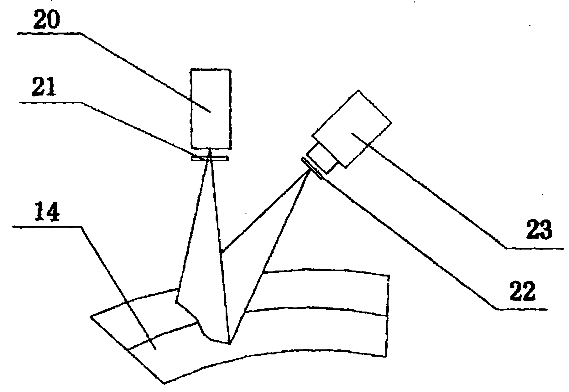
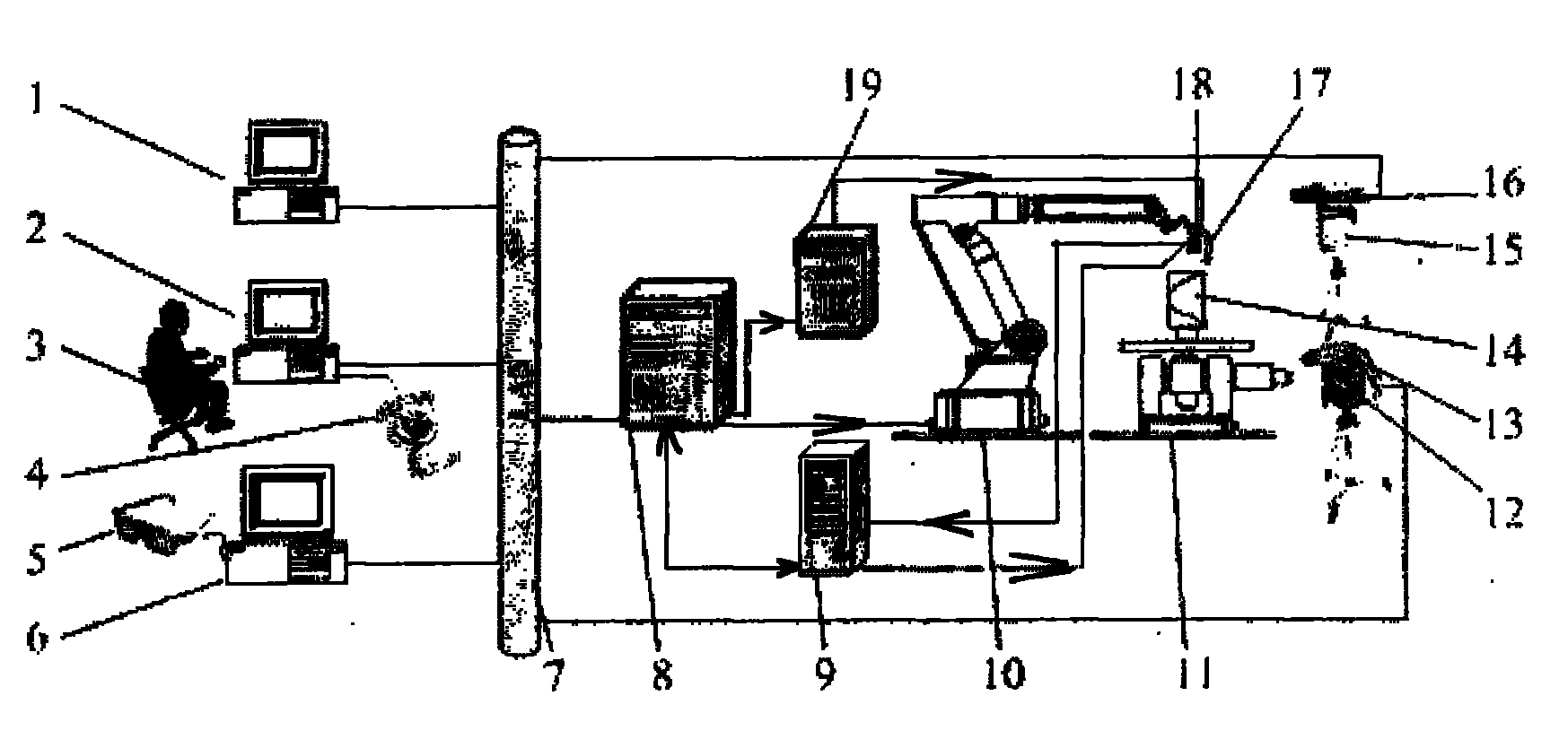
[0011] Specific implementation mode one: combine figure 1 with figure 2 Describe this embodiment, the system of this embodiment consists of a macro vision display 1, a central monitoring man-machine interface 2, a space mouse 4, liquid crystal shutter glasses 5, a stereo vision display 6, an industrial Ethernet 7, a robot controller 8, and a laser vision control 9, robot 10, working platform 11, first controllable pan / tilt 12, binocular camera 13, second controllable pan / tilt 15, macro zoom camera 16, welding torch 17, laser vision sensor working head 18 and welding power source 19 , the space mouse 4 is connected with the central monitoring man-machine interface 2, and the central monitoring man-machine interface 2 is connected with the robot controller 8 through the industrial Ethernet 7, and the liquid crystal shutter glasses 5 are connected with the stereo vision display 6, and the stereo Visual display 6 is connected with binocular camera 13 by industrial ethernet 7, an...

specific Embodiment approach 2

[0013] Specific implementation mode two: combination figure 1 The present embodiment will be described. The robot 10 of the present embodiment has six degrees of freedom. Other components and steps are the same as those in Embodiment 1.

specific Embodiment approach 3

[0014] Specific implementation mode three: combination figure 1 Describe this embodiment, the method of this embodiment is completed by the following steps:

[0015] Step 1: The macro zoom camera 16 collects two-dimensional video images, and transmits the two-dimensional video images to the macro vision display 1 through the industrial Ethernet 7, and the operator 3 adjusts the field of view in the central monitoring human-machine interface 2 at the local end;

[0016] Step 2: The operator 3 operates the space mouse 4 to issue a control command on the central monitoring human-machine interface 2, and transmits it to the remote robot controller 8 through the industrial Ethernet 7 to control the movement of the remote robot 10, and the robot 10 guides the welding torch 17 Move to the vicinity of 30-40mm above the welding seam, and at the same time, the robot controller 8 transmits the pose matrix of the welding gun 17 to the central monitoring human-machine interface 2 at the lo...


PUM


Abstract

The invention relates to a robot remote control welding system and a method used for remote welding, which relate to a robot remote control welding system and a method. The invention has the goal of solving the problems that in the existing remote control welding process, the real-time requirement of the welding process is high, the adaptability of the autonomous control remote control welding is low, the visual feedback of the remote welding is poor, and the system universality on welding tasks is low. The system has the technical scheme that a center monitoring human-machine interface is connected with a robot controller, and the robot controller is respectively connected with a laser visual controller, a robot and a welding power supply. The method has the technical scheme that a binocular camera transmits a welding environment image to a three-dimensional visual display, operators obtain the deep information of the remote end environment and guide a welding gun to move to the welding seam starting position, and four work modes: the direct control work mode, the remote control teaching work mode, the laser visual display tracking work mode or the human-machine cooperation sharing control work mode can be respectively adopted for completing the remote control welding. The invention is used for robot remote control welding.

Description

technical field [0001] The invention relates to a robot remote control welding system and method. Background technique [0002] Welding applications are essential in the underwater construction of marine engineering, the installation and maintenance of nuclear power plants, the establishment of future space stations, and the installation, maintenance and repair of equipment in extreme environments and dangerous environments. In these extreme environments, the operator cannot directly weld on site, and must implement remote welding. Remote control welding means that people can remotely monitor and control the welding equipment and welding process according to various sensor information on site in a safe environment far away from the site to complete the welding operation. There is a big difference between remote control welding and remote control operations such as grasping and assembly: the real-time requirements of the welding process are high, and the time delay seriously...

Claims


Application Information

Patent Timeline
IPC IPC(8): B23K37/00
Inventor 李海超高洪明张广军吴林
Owner HARBIN INST OF TECH
Why Eureka
Try Eureka