
Polar coordinate numerical control woodworking basket milling machine

A polar coordinate and woodworking technology, applied in the field of polar coordinate CNC woodworking basket milling machine, can solve the problems of increased floor space, low processing efficiency, low processing efficiency, etc. high quality effect

Inactive Publication Date: 2010-08-04
SHENZHEN HUAZHONG NUMERICAL CONTROL
View PDF6 Cites 12 Cited by
  • Summary
  • Abstract
  • Description
  • Claims
  • Application Information

AI Technical Summary

Problems solved by technology

[0003] 1) The machining accuracy cannot be guaranteed. In addition to being affected by fixed factors such as machine tools and cutting tools, the machining accuracy is also affected by uncertain factors such as anti-shape molds and profiles, making it difficult to guarantee the processing quality;
[0004] 2) Each workpiece requires a special anti-shape mold, which has a long design cycle and high cost;
[0005] 3) The processing efficiency is low, because the master model always exerts force on the pulley and the cylindrical milling cutter in the X-axis direction, resulting in limited rotation speed and low processing efficiency;
[0006] 4), the machine volume is large, and the existing woodworking basket milling machine is equipped with two workbenches, which increases the occupied area;
[0007] 5), the existing woodworking basket milling machine is limited to two-axis milling processing, cannot perform three-dimensional processing, and the scope of use is limited

Method used


Image

  • Polar coordinate numerical control woodworking basket milling machine
  • Polar coordinate numerical control woodworking basket milling machine
  • Polar coordinate numerical control woodworking basket milling machine

Examples


Embodiment Construction

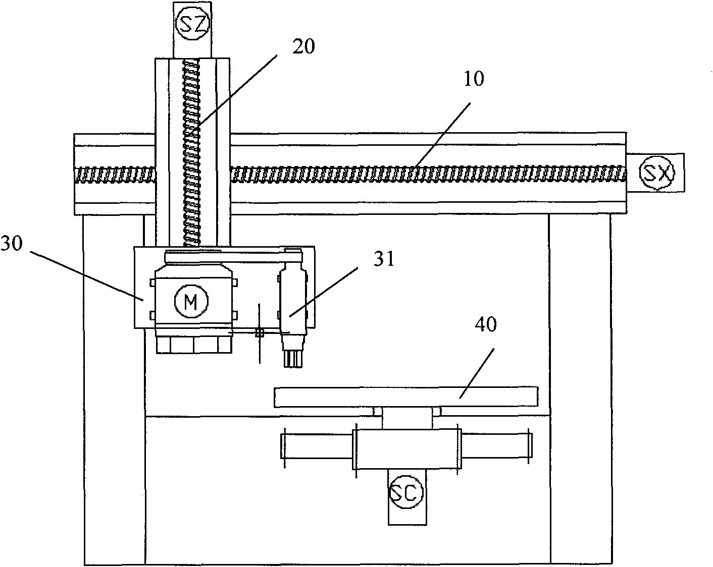
[0036] The polar coordinate numerical control woodworking basket milling machine of the present invention includes a mechanical mechanism and a numerical control mechanism for controlling the mechanical mechanism. Such as figure 2 As shown, it is a schematic structural view of the mechanical mechanism in the polar coordinate CNC woodworking basket milling machine of the present invention, and the mechanical mechanism includes the first screw mandrel 10, the second screw mandrel 20, the knife rest 30 and a circular workbench 40, and also includes :

[0037] The first servo motor SX that is arranged in the X-axis direction and drives the knife rest 30 to move horizontally in the X-axis direction by driving the first screw mandrel 10 to rotate; is arranged in the Z-axis direction and drives the knife rest by driving the second screw mandrel 20 to rotate 30 is the second servo motor SZ that moves vertically in the Z-axis direction; the third servo motor SC that drives the workta...


PUM


Abstract

The invention relates to a polar coordinate numerical control woodworking basket milling machine which comprises a mechanical mechanism and a numerical control mechanism. The mechanical mechanism comprises a first screw rod, a second screw rod, a tool holder, a circular worktable, a first servo motor, a second servo motor, a third servo motor, a cylinderical tool and a spindle motor, wherein the first servo motor is arranged in the X-axis direction and drives the tool holder to horizontally move in the X-axis direction by driving the first screw rod; the second servo motor is arranged in the Z-axis direction and drives the tool holder to vertically move in the Z-axis direction by driving the second screw rod; the third servo motor drives the worktable to rotate by taking the center thereof as a rotary shaft; the cylinderical tool and the spindle motor used for driving the cylinderical tool to rotate are installed on the tool holder; the horizontal plane of the worktable forms a polar coordinate, a pole is the rotary shaft of the worktable, a polar axis is irradiates rays along the direction of the X axis by taking the rotary shaft of the worktable as a starting point, a polar angle is a rotation angle of the worktable, and a polar radius is a distance from the rotary shaft of the worktable to the center of the cylinderical tool. By adopting a numerical control technology, the invention can carry out three-dimensional stereo machining with high machining efficiency.

Description

technical field [0001] The invention relates to the technical field of woodworking basket milling machines, and more specifically, relates to a polar coordinate numerical control woodworking basket milling machine. Background technique [0002] Woodworking basket milling machines generally refer to machines that process wood surfaces according to specific requirements. At present, woodworking basket milling machines generally use anti-shape machinery, such as figure 1 As shown, the mechanical execution part of the existing woodworking basket milling machine is mainly a workbench I and a workbench II with the same center of rotation, the workbench I is provided with a pulley, and the workbench II is provided with a cylindrical milling cutter. In addition, A cam is also provided, and the cam drives the pulley and the cylindrical milling cutter to translate synchronously in the X direction, and makes the pulley and the cylindrical milling cutter have the same distance from the...

Claims


Application Information

Patent Timeline
Patent Type & Authority Applications(China)
IPC IPC(8): B27C5/02
Inventor 谢星葵杨虎李玉明
Owner SHENZHEN HUAZHONG NUMERICAL CONTROL
Learn More