Self-propelled aerial working platform vehicle chassis

A high-altitude work platform and vehicle chassis technology, applied in the directions of axles, wheels, vehicle parts, etc., can solve the problems of reduced driving force, low work efficiency, complex structure, etc., and achieve improved stability, fast response speed, and high control precision. Effect

Active Publication Date: 2010-08-04
威海怡和专用车有限公司
View PDF7 Cites 4 Cited by
  • Summary
  • Abstract
  • Description
  • Claims
  • Application Information

AI Technical Summary

Problems solved by technology

[0002] As we all know: self-propelled aerial work platforms are widely used in shipbuilding, engineering construction, industrial installation, equipment maintenance and other industries. When the rigid chassis encounters such working conditions, the tires will be suspended from the ground, etc., which reduces the driving force and may cause the risk of overturning. When using four-wheel drive, the driving force is acceptable, and the two-wheel drive chassis can adapt to the working conditions. Poor, therefore, the chassis swing bridge is required to keep the driving wheels in contact with the ground all the time to ensure the driving force and adapt to complex working conditions
[0003] At the same time, in order to improve the working stability of the self-propelled aerial work platform, it is necessary to increase the wheelbase, but the wheelbase is fixed and the larger chassis has poor passability. Shrink the wheelbase when walking or transferring
[0004] At present, most wheelbase telescopic devices use jack cylinders (jacking cylinders) to raise the vehicle frame to a certain height when the vehicle is stopped, so that the tires can be stretched off the ground, and then the telescopic tie rods are locked manually after the stretching is in place. Lower the frame again, the work efficiency is low and the structure is complicated
The patent 95116054.0 (priority US08 / 314.763) applied by U.S. Kidd Company in China provides a retractable tie rod in the retractable telescopic axle assembly. It still has the disadvantages of complex structure and low work efficiency
Chinese patent ZL200720177872.0 provides a chassis walking system for high-altitude operation vehicles. Its wheel base telescopic mechanism can automatically complete the wheel base expansion and contraction during driving. The telescopic oil cylinder is a double-piston rod structure, and the telescopic oil cylinder is fixed. On the chassis, the production and installation of the oil cylinder are more complicated
However, the three-position six-way control valve is installed on the rear axle and the operating rod of the control valve is hinged to the rear axle, so it is difficult to form feedback, and there are deficiencies in action response speed and control accuracy, and the expansion and contraction of the wheelbase also uses jacking cylinders System, complex structure, low work efficiency

Method used


Image

  • Self-propelled aerial working platform vehicle chassis
  • Self-propelled aerial working platform vehicle chassis
  • Self-propelled aerial working platform vehicle chassis

Examples


Embodiment 1

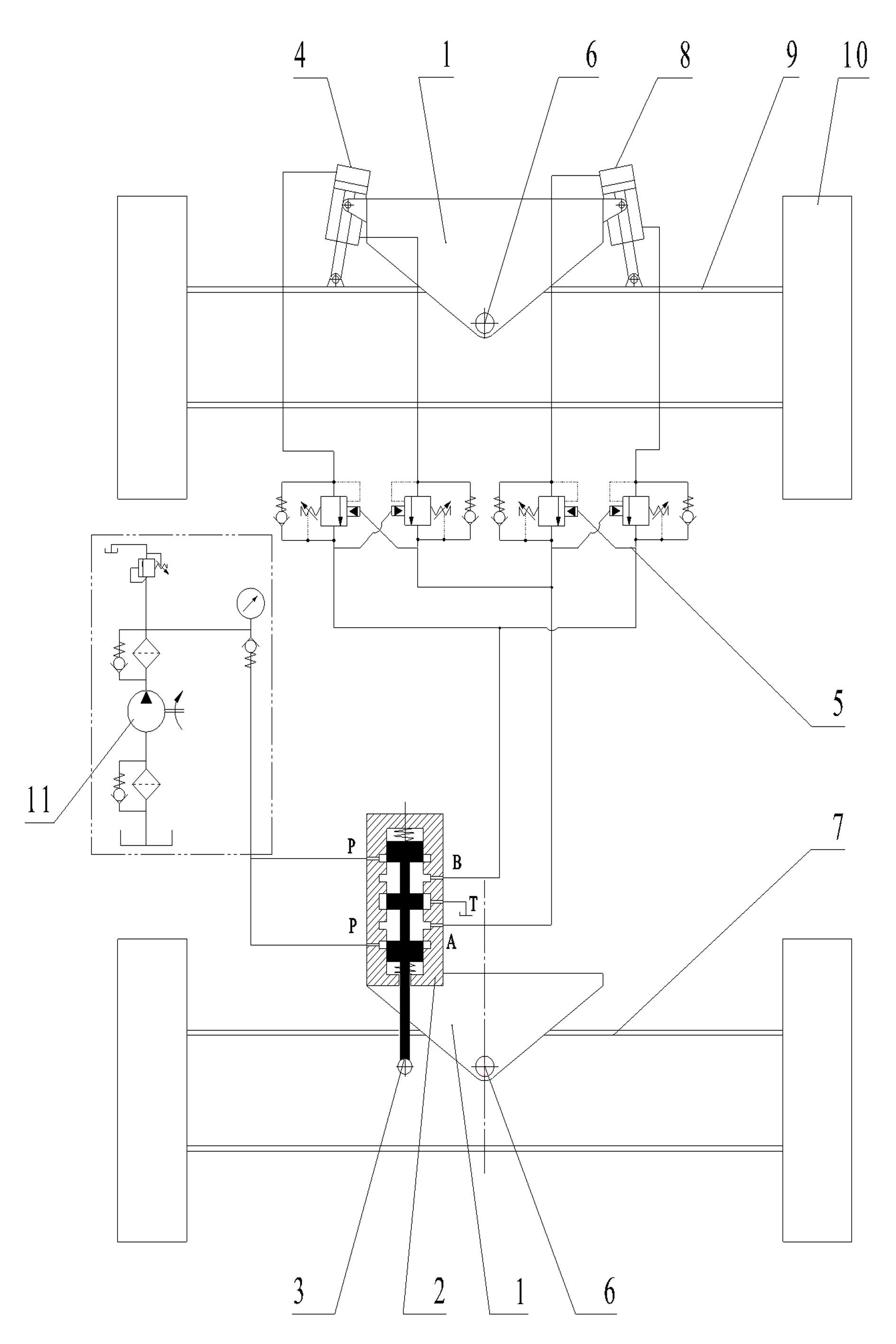
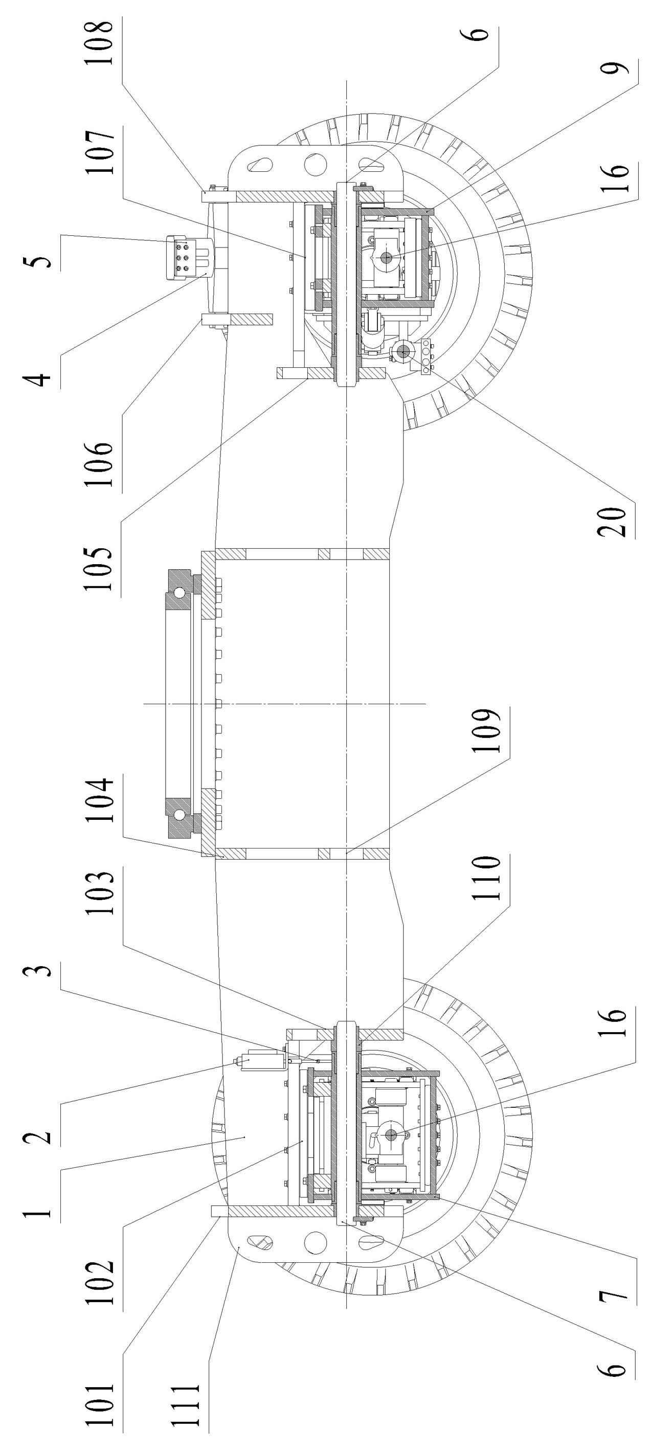
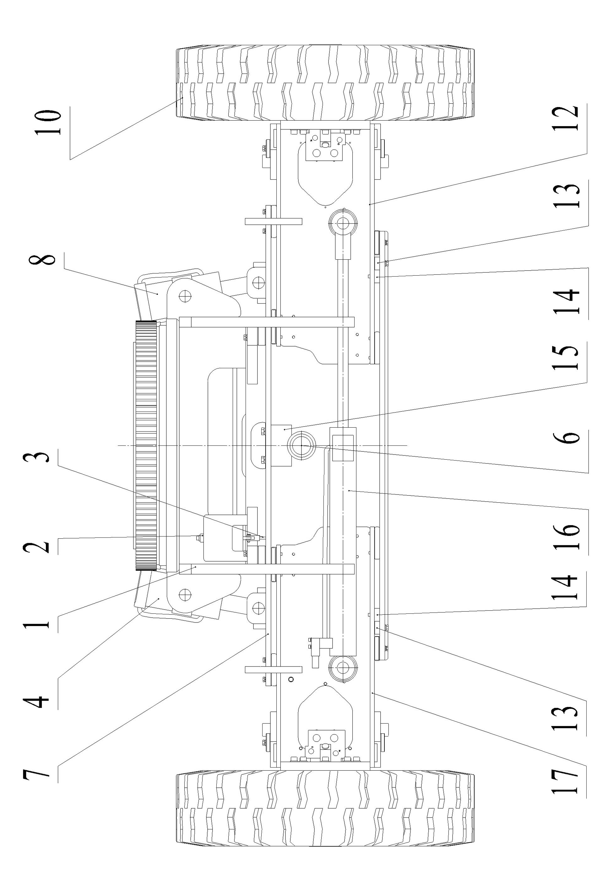
[0023] like figure 1 As shown, a vehicle frame 1 is provided, and the vehicle frame 1 is respectively hinged with the front axle 9 and the rear axle 7 through the chassis main shaft 6, and the rear axle 7 is free to swing around the chassis main shaft 6 within a set range, so that the rear axle 7 left and right tires 10 Always in contact with the ground, the front axle 9 swings around the chassis main shaft 6 driven by the left servo hydraulic cylinder 4 and the right servo hydraulic cylinder 8, the cylinder body of the left servo hydraulic cylinder 4 is hinged with the vehicle frame 1, and the left servo hydraulic cylinder The piston rod of the cylinder 4 is hinged with the front axle 9, the cylinder body of the right follow-up hydraulic cylinder 8 is hinged with the vehicle frame 1, the piston rod of the right follow-up hydraulic cylinder 8 is hinged with the front axle 9, and the hydraulic energy source 11 uses constant pressure as four sides Two P ports of spool valve 2 su...

Embodiment 2

[0032] like Figure 5 As shown, a vehicle frame 1 is provided, and the vehicle frame 1 is respectively hinged with the front axle 9 and the rear axle 7 through the chassis main shaft 6, the rear axle 7 is free to swing around the chassis main shaft 6 within a set range, and the left and right tires 10 of the rear axle 7 are always In contact with the ground, the front axle 9 swings around the chassis main shaft 6 driven by the left servo hydraulic cylinder 4 and the right servo hydraulic cylinder 8, the cylinder body of the left servo hydraulic cylinder 4 is hinged with the vehicle frame 1, and the left servo hydraulic cylinder The piston rod of 4 is hinged with the front axle 9, the cylinder body of the right follow-up hydraulic cylinder 8 is hinged with the vehicle frame 1, the piston rod of the right follow-up hydraulic cylinder 8 is hinged with the front axle 9, and the hydraulic energy source 11 is a four-sided slide in a constant pressure manner. The P port of the valve ...


PUM


Abstract

The invention relates to a self-propelled aerial working platform vehicle chassis, which belongs to the field of engineering machinery. The chassis is provided with a frame, the frame is respectively articulated with a front axle and a rear axle through main chassis shafts, the body of a four-sided slide valve is fixed on one side of the frame, a four-sided slide valve core pull rod is articulated with the rear axle, the body of a left servo hydraulic cylinder is articulated with the frame, the piston rod of the left servo hydraulic cylinder is articulated with the front axle, the body of a right servo hydraulic cylinder is articulated with the frame, the piston rod of the right servo hydraulic cylinder is articulated with the front axle, a hydraulic power source supplies oil to the four-sided slide valve under constant pressure, one oil outlet of the four-sided slide valve is connected with the piston cavity of the right servo hydraulic cylinder and the rod cavity of the left servo hydraulic cylinder via a balance valve, and the other oil outlet of the four-sided slide valve is connected with the rod cavity of the right servo hydraulic cylinder and the piston cavity of the left servo hydraulic cylinder. The invention adopts the mechano-hydraulic servo control mechanism to ensure that tyres can follow the ground to ensure driving force, and the tread can be automatically increased and decreased in the process of running.

Description

technical field [0001] The invention relates to the field of engineering machinery, and in particular relates to a chassis of a self-propelled aerial work platform, in particular to a chassis that adopts a machine-hydraulic servo control mechanism to realize the movement of tires and the ground to ensure driving force. Background technique [0002] As we all know: self-propelled aerial work platforms are widely used in shipbuilding, engineering construction, industrial installation, equipment maintenance and other industries. When the rigid chassis encounters such working conditions, the tires will be suspended from the ground, etc., which reduces the driving force and may cause the risk of overturning. When using four-wheel drive, the driving force is acceptable, and the two-wheel drive chassis can adapt to the working conditions. Poor, therefore, it is necessary to swing the bridge of the chassis so that the driving wheels are always in contact with the ground to ensure th...

Claims


Application Information

Patent Timeline
Patent Type & Authority Applications(China)
IPC IPC(8): B60K17/34B60B35/14
Inventor 杨立新王成强孙志杰宋治春曹政林同信张汝秀邹德伟
Owner 威海怡和专用车有限公司
Why Eureka
Try Eureka