
Biomass preventing corrosion of superheater and garbage power generation boiler

A waste-to-energy and biomass technology, applied to steam boilers, steam generation, lighting and heating equipment, etc., can solve problems such as reducing boiler life, accelerating corrosion, superheater corrosion, etc., achieving simple construction and maintenance, and reducing chlorine content , the effect of prolonging the service life

Inactive Publication Date: 2010-08-04
朴显泽 +2
View PDF5 Cites 9 Cited by
  • Summary
  • Abstract
  • Description
  • Claims
  • Application Information

AI Technical Summary

Problems solved by technology

[0002] The biggest problem of power generation boilers burning biomass and garbage is that the superheater is severely corroded. One of the important reasons is that the smoke generated during the combustion of biomass and garbage contains a large amount of chloride, HCl, and Cl. 2 Harmful gases, such as harmful gases, have a strong corrosive effect on alloy superheater tubes. At present, power generation boilers burning biomass and garbage only set secondary air at the front and rear arches of the furnace, and the distance between the front and rear arches is relatively large. The mixed combustion of wind and flue gas is not sufficient, the residence time of flue gas in the furnace is short, and a large amount of chloride and HCl, Cl contained in flue gas 2 Such harmful gases enter the flue without treatment, causing corrosion to the alloy superheater tube, especially under continuous ultra-high temperature conditions, which will accelerate the corrosion rate. After the boiler has been running for about a year, the superheater will burst. Replacing a new superheater reduces boiler life and increases boiler operation and maintenance costs
A 110t / h high-temperature and high-pressure straw direct-fired boiler was disclosed in the fifth issue of "Industrial Boiler" in 2008, "Introduction to Domestic Straw Direct-fired Boilers". Corrosion of alloy materials has a certain effect on protecting the superheater, but it still cannot solve the problem of chlorine element corrosion on the superheater

Method used


Image

  • Biomass preventing corrosion of superheater and garbage power generation boiler
  • Biomass preventing corrosion of superheater and garbage power generation boiler
  • Biomass preventing corrosion of superheater and garbage power generation boiler

Examples


Embodiment 1

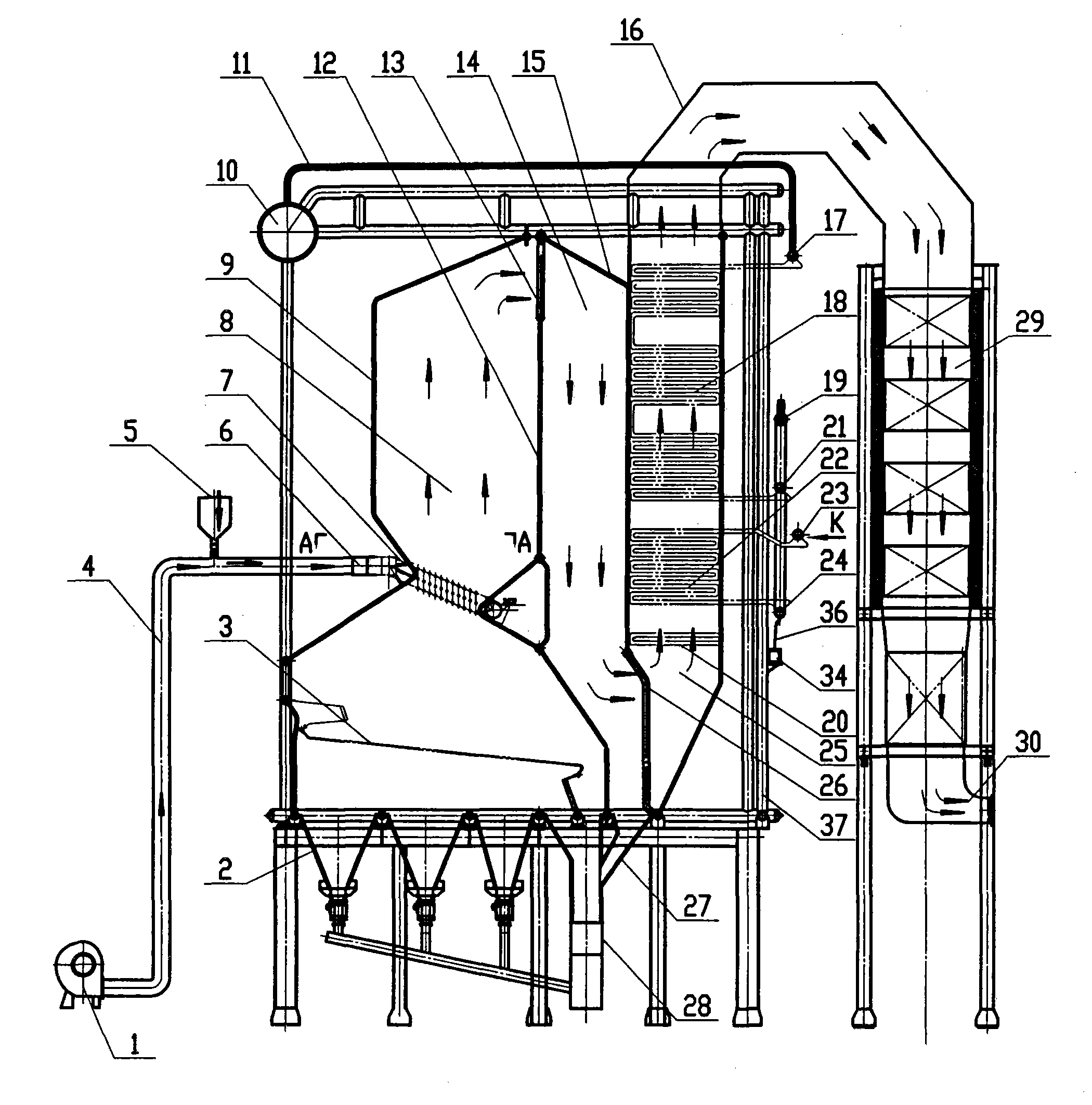
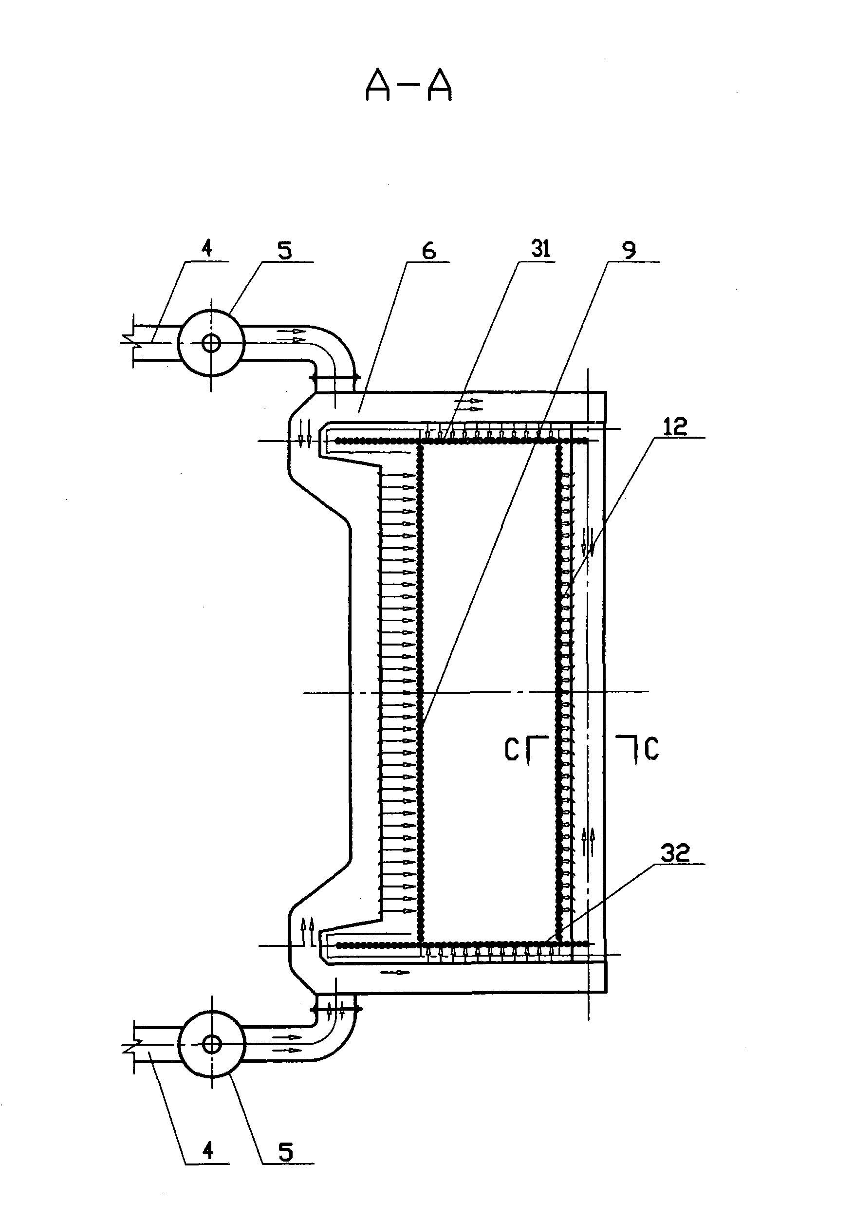
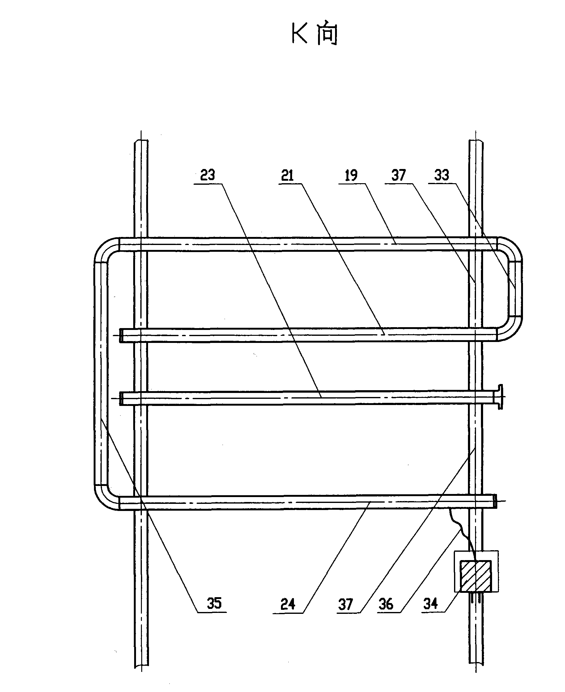
[0029] Example 1: A 75t waste-to-energy boiler that prevents superheater corrosion, including the body of the waste-to-energy boiler, wherein the secondary air box is arranged around the arch of the furnace 8 to form a surrounding secondary air; on the secondary air main pipe 4, set A limestone powder funnel 5 with a material control valve; the distance between the front and rear arches of the furnace 8 is 2m; the convection low-temperature superheater pipe 18 and the high-temperature superheater pipe 22 are arranged in the shaft flue II 25; On the pipe wall of the downcomer 37 at the inlet header 24 of the device, a box body is arranged, and the box body is fixedly connected with the pipe wall of the downcomer 37, and a zinc block 34 is placed in the box, and is connected to the inlet of the high-temperature superheater through a copper wire. The headers 24 are connected.

Embodiment 2

[0030] Example 2: A 35t biomass power boiler that prevents superheater corrosion, including the body of the biomass power boiler, wherein the secondary air box is arranged around the arch of the furnace 8 to form a surrounding secondary air, on the secondary air main pipe 4 , a limestone powder funnel 5 with a material control valve is set, the distance between the front and rear arches of the furnace 8 is: 1.5m; the convection low-temperature superheater tube 18 and the high-temperature superheater tube 22 are arranged in the shaft flue II 25; On the tube wall of the downcomer 37 near the inlet header 24 of the high-temperature superheater, a box body is arranged, and the box body is fixedly connected with the tube wall of the downcomer 37, and a zinc block 34 is placed in the box, and the copper wire and the The inlet headers 24 of the high temperature superheater are connected to each other.

Embodiment 3

[0031] Embodiment 3: A 20t biomass power boiler for preventing superheater corrosion, including a biomass power boiler body, wherein a box is set on the tube wall of the downcomer 37 near the inlet header 24 of the high temperature superheater. It is fixedly connected with the pipe wall of the downcomer 37, and a zinc block 34 is placed in the box, and is connected with the inlet header 24 of the high-temperature superheater through a copper wire 36.


PUM


Abstract

The invention discloses a biomass preventing the corrosion of superheater and a garbage power generation boiler, belonging to power generation equipment using renewable sources as fuel. The garbage power generation boiler comprises a boiler body, characterized in that: a circular secondary air box is arranged around a furnace arc part of a hearth and the spacing between a front arc and a rear arc is appropriately shortened; a limestone powder funnel is arranged at a secondary air main, limestone powder is fully mixed with smoke gas under the driving of secondary air so as to reduce the content of chlorine in the smoke gas; a shaft flue I, a shaft flue II and a shaft flue III are arranged sequentially at a high-temperature smoke gas outlet of the hearth, a superheater pipe is arranged inside the shaft flue II and controlled within 800 DEG C; a box body for fixing a zinc spelter is arranged at a descending pipe wall which is adjacent to a high-temperature superheater inlet header and a low-temperature superheater outlet header, and the zinc spelter is connected with the high-temperature superheater inlet header or the low-temperature superheater outlet header via conducting wires; the garbage power generation boiler has obvious effect in preventing the corrosion of the superheater, prolongs the service life of the superheater and includes low cost, simple and convenient construction and maintenance.

Description

technical field [0001] The invention relates to a power generation equipment using renewable energy as fuel, in particular to a power generating boiler using biomass or garbage as fuel. technical background [0002] The biggest problem of power generation boilers burning biomass and garbage is that the superheater is severely corroded. One of the important reasons is that the smoke generated during the combustion of biomass and garbage contains a large amount of chloride, HCl, and Cl. 2 Harmful gases, such as harmful gases, have a strong corrosive effect on alloy superheater tubes. At present, power generation boilers burning biomass and garbage only set secondary air at the front and rear arches of the furnace, and the distance between the front and rear arches is relatively large. The mixed combustion of wind and flue gas is not sufficient, the residence time of flue gas in the furnace is short, and a large amount of chloride and HCl, Cl contained in flue gas 2 Such harmf...

Claims


Application Information

Patent Timeline
Patent Type & Authority Applications(China)
IPC IPC(8): F22B31/08F23L9/00F23M5/06F23J7/00C23F13/02
Inventor 朴显泽林英杰尤克
Owner 朴显泽
Learn More