DC-DC power supply device, voltage regulation method and network equipment

A DC-DC and power supply device technology, applied in the electronic field, can solve the problems of unfavorable test and test failure recurrence, lack of adjustment of the output voltage of DC-DC switching power supply, and poor use conditions, etc., to achieve convenient product testing and inspection work, The effect of improving testability and improving stability

Active Publication Date: 2010-08-04
RUIJIE NETWORKS CO LTD
View PDF0 Cites 22 Cited by
  • Summary
  • Abstract
  • Description
  • Claims
  • Application Information

AI Technical Summary

Problems solved by technology

[0012] the above image 3 The implementation scheme recorded in can stabilize the output voltage, but it does not have the function of adjusting the output voltage of the DC-DC switching power supply. Figure 4 The implementation documented in is image 3 The improvement of the scheme shown can realize the adjustment of the output voltage value, but it does not have the function of realizing the synchronous adjustment of the output of multiple different DC-DC switching power supplies, because under the existing technology, when each chip is interconnected, the output voltage is synchronized. The increase of the offset or the decrease of the step offset at the same time conform to the worst use conditions in the actual application, so that the circuit works in the worst use conditions of various combinations, and it is convenient for engineers to find design hidden dangers and circuit problems early
On the other hand, if the Figure 4 As shown in the implementation scheme, when adjusting the output voltage offset, the power must be cut out of the box before implementation, thus destroying the continuity of the overall circuit test process, and the circuit cannot be accurately restored to the previous output after manual single-channel adjustment. state, and it is not conducive to the recurrence of test failures in the later stage

Method used


Image

  • DC-DC power supply device, voltage regulation method and network equipment
  • DC-DC power supply device, voltage regulation method and network equipment
  • DC-DC power supply device, voltage regulation method and network equipment

Examples


Embodiment Construction

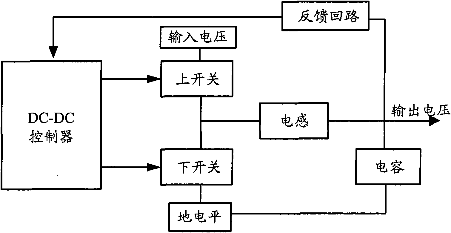
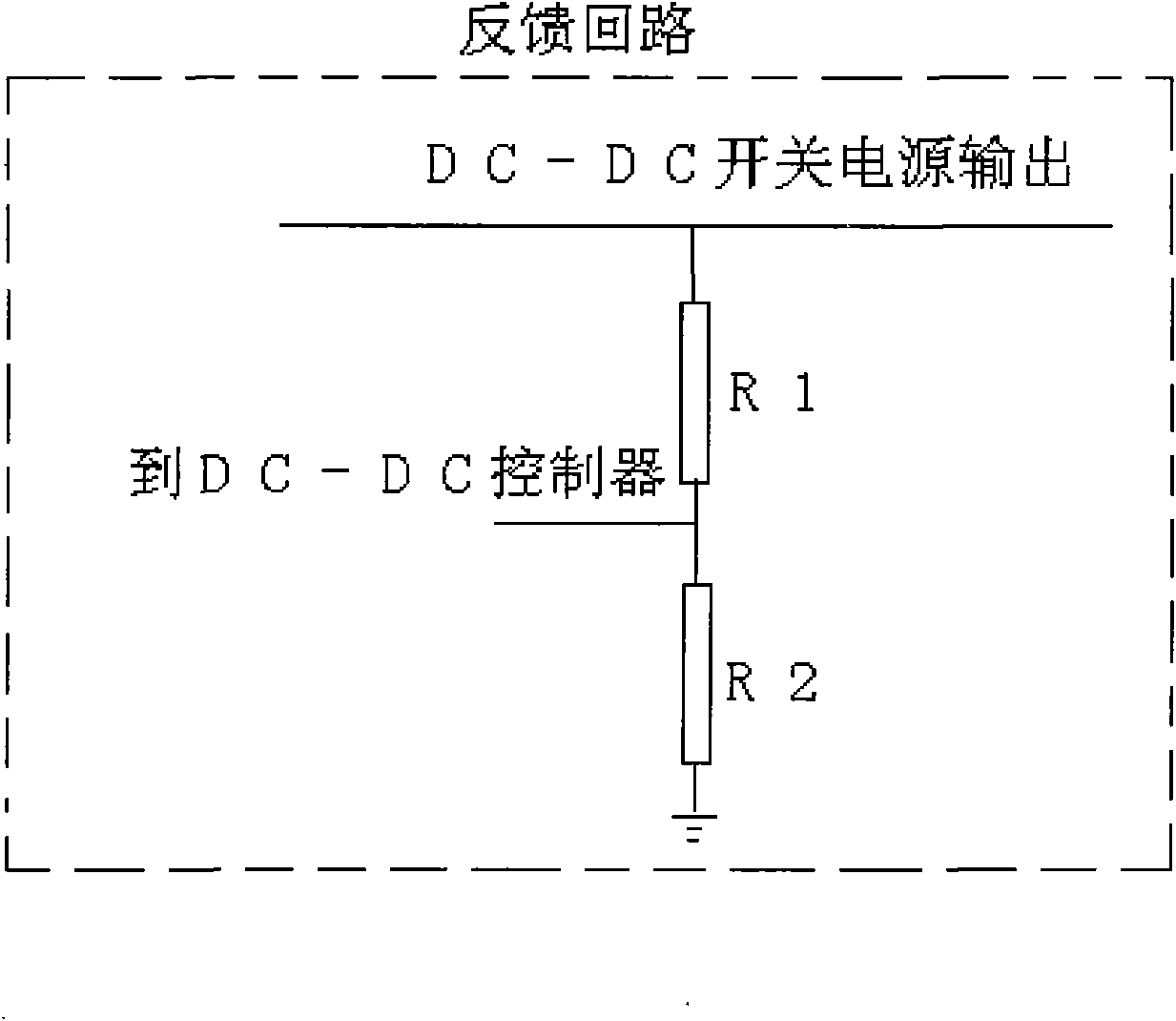
[0028] For the DC-DC power supply device, in order to improve the testability of the circuit, in the embodiment of the present invention, a DC-DC switching power supply module, a first feedback resistor and a second feedback resistor are set in the DC-DC power supply device, and the One end of the first feedback resistor is connected to the power supply output end of the DC-DC switching power supply module, the other end is grounded through the second feedback resistor, and the connection point between the first feedback resistor and the second feedback resistor is connected to the DC-DC switching power supply module. Feedback voltage input, also includes:

[0029] At least one adjustment module, each adjustment module includes at least one set of voltage resistors, the at least one set of voltage resistors includes: a first voltage divider resistor, a second voltage divider resistor, a first switch and a second switch, the first A branch in which a voltage dividing resistor i...


PUM


Abstract

The invention relates to the technical field of electronics and discloses a DC-DC power supply device, a voltage regulation method and network equipment in order to improve the testability of circuits. In the invention, at least one regulation module and a control module are arranged in the DC-DC power supply device, wherein the control module controls the conduction states of upper and lower switch tubes in a resistor array in the regulation module so as to regulate the offset of an output voltage to control the size of the output voltage. Thus, the synchronous regulation of one or more DC-DC switch power supply modules can be realized without manual box opening and power-interrupting operation and the precision regulation of the output voltages of the DC-DCs switch power supply modules is realized without a large amount of circuit hardware regulation and change, so that the testability of the circuit and operation smoothness of the whole circuit test process are improved effectivelyand the product test and examination work is very convenient. The invention also discloses the power supply method and the network equipment.

Description

technical field [0001] The present invention relates to the field of electronic technology, in particular to a DC-DC power supply device, a voltage adjustment method and network equipment Background technique [0002] Usually, to make an integrated chip work stably and reliably, its power supply voltage needs to be controlled within a set range, that is, the power supply voltage value is required to be between a minimum value and a maximum value. If the power supply voltage of the chip is less than the minimum value or greater than the maximum value, it will cause the chip to work unstable or even be damaged. [0003] In the design stage of the power supply system of the product, the power supply voltage circuit of each chip is formed after theoretical calculation with reference to the design scheme and the power supply requirements of each chip. However, due to the differences in device parameters in the circuit, there may be differences between the theoretical design value...

Claims


Application Information

Patent Timeline
Patent Type & Authority Applications(China)
IPC IPC(8): H02M3/28
Inventor 任谦刘贤兵
Owner RUIJIE NETWORKS CO LTD
Why Eureka
Try Eureka