Dispersive modulation-based non-mirror image optimal frequency domain imaging system and method

An imaging system and dispersion technology, applied in medical science, sensors, diagnostic recording/measurement, etc., can solve the problems of reducing imaging speed, expensive equipment, impact, etc., achieve zero group delay and dispersion modulation, ensure compactness and Reliability, the effect of keeping the optical path constant

Inactive Publication Date: 2010-08-18
ZHEJIANG UNIV
View PDF2 Cites 39 Cited by
  • Summary
  • Abstract
  • Description
  • Claims
  • Application Information

AI Technical Summary

Problems solved by technology

[0005] All of the above methods have their inherent disadvantages. For example, the multi-step phase shifting method using piezoelectric ceramic drivers requires multiple measurements of the same position, which reduces the imaging speed, and requires high phase stability, and is susceptible to the influence of various environmental disturbances on the phase; the method of using electro-optic phase modulators and acousto-optic phase modulators needs to introduce more complex and expensive instruments and equipment, and the system data acquisition The speed puts forward strict requirements; the method of using 3×3 fiber coupler is susceptible to the influence of temperature on the coupling coefficient, resulting in the inaccuracy of restoring the complex interference spectrum, which affects the overall complex conjugate suppression rate; the existing proposed method uses dispersion to remove The complex conjugate image method needs to rely on a complex iterative algorithm, and the simplification of the algorithm also reduces the complex conjugate suppression rate

Method used


Image

  • Dispersive modulation-based non-mirror image optimal frequency domain imaging system and method
  • Dispersive modulation-based non-mirror image optimal frequency domain imaging system and method
  • Dispersive modulation-based non-mirror image optimal frequency domain imaging system and method

Examples


Embodiment Construction

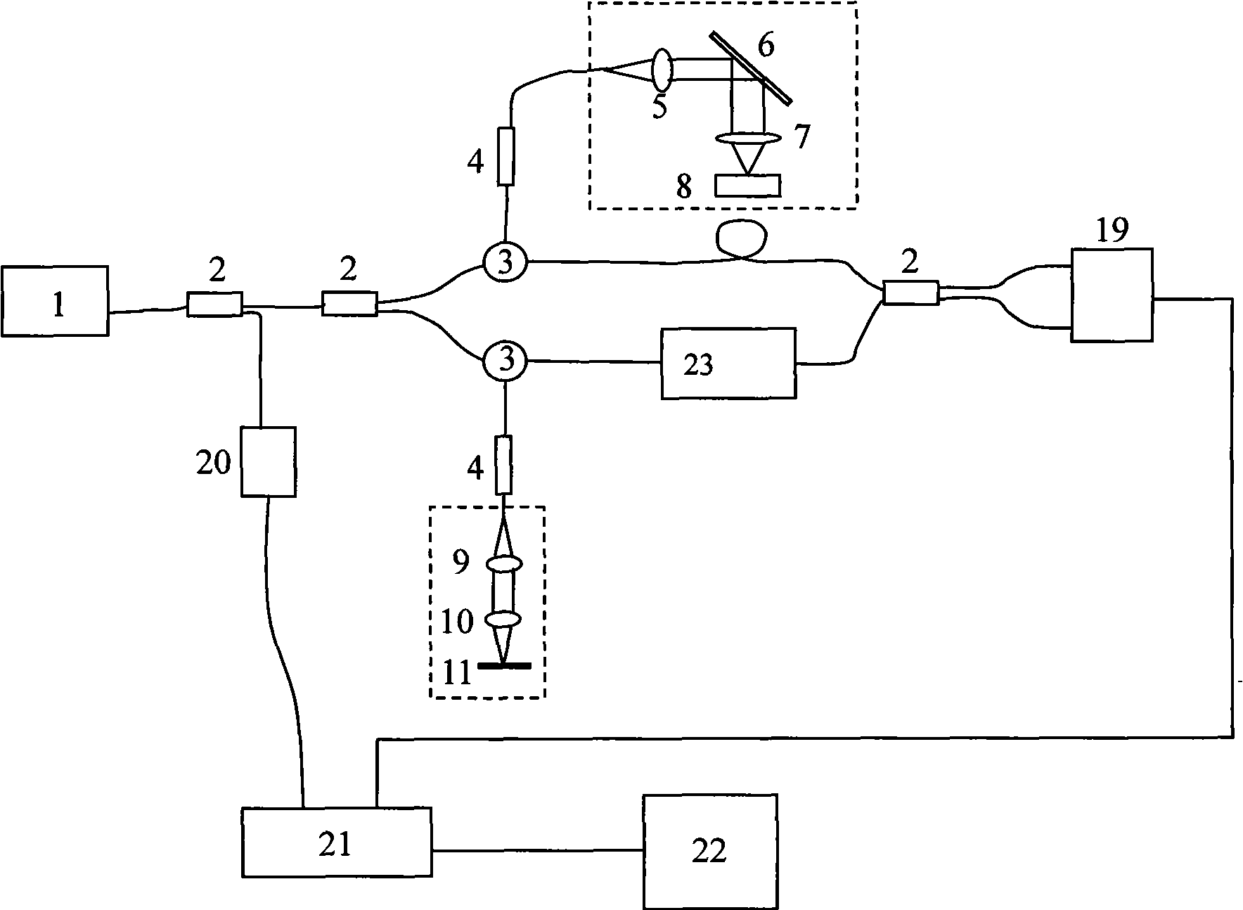
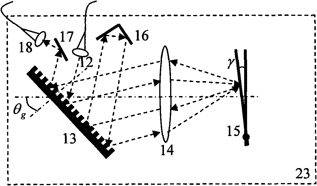
[0021] The mirrorless optical frequency domain imaging method based on dispersion modulation in the present invention sets a transmission optical scanning delay line on the reference arm of the optical frequency domain imaging system, realizes dispersion modulation while maintaining the same optical path of the reference arm, and ensures different dispersion states The identity of the axial position of the lower sample. By rapidly changing the rotation angle of the galvanometer in the transmission optical scanning delay line, two sets of interference spectrum signals of the same sample in two dispersion states are obtained. The dispersion of the corresponding imaginary part is compensated by multiplying the corresponding dispersion compensation factor, and the two sets of interference spectra after dispersion compensation are subtracted, and then the dispersion compensation is performed again, and then the Fourier inverse transform is performed to obtain the real reflection sig...


PUM


Abstract

The invention discloses a dispersive modulation-based non-mirror image optimal frequency domain imaging system and a dispersive modulation-based non-mirror image optimal frequency domain imaging method. In the system, a transmission-type optimal scanning delay line is arranged in a reference arm for modulating dispersion so as to ensure the identity of the axial positions of a sample under different dispersion states; by changing a rotation angle of an oscillating mirror in the transmission optimal scanning delay line, the rapid modulation of dispersion is realized, and two group of interference spectrum signals of the same sample are acquired under two different dispersion states; the two group of acquired interference spectrum signals are respectively multiplied by corresponding dispersion compensation factors so as to accurately compensate the dispersion of imaginary part subjected to corresponding Fourier transform; subtraction operation is performed on the two group of interference spectrum signals subjected to dispersion compensation, then, the imaginary part of the corresponding repeated reflection signal disappears, and the real part still contains the dispersion factor; and finally, the interference spectrum signals subjected to subtraction are subjected to dispersive compensation again and then subjected to Fourier inverse transformation so as to obtain the actual reflection signal of the sample for non-mirror image reconstruction of the sample image.

Description

technical field [0001] The invention relates to optical coherence tomography (OCT) technology, in particular to a mirrorless optical frequency domain imaging system and method based on dispersion modulation. Background technique [0002] Optical coherence tomography (OCT) imaging technology is a new type of optical imaging technology that can perform non-invasive, non-contact, high-resolution in vivo imaging of the tissue structure and physiological functions of the tested living sample. It has broad application prospects in the field of early diagnosis of diseases and in vivo biopsy. [0003] The optical frequency domain imaging system is a type of optical coherence tomography system. It uses a high-speed frequency-swept laser source and a point detector to collect axial interference spectral signals of the sample. The reference arm is composed of a fixed plane mirror and does not require axial scanning. , the axial depth information of the sample can be obtained by perfor...

Claims


Application Information

Patent Timeline
Patent Type & Authority Applications(China)
IPC IPC(8): A61B5/00
Inventor 丁志华吴彤陈明惠王玲徐磊王凯孟婕王川
Owner ZHEJIANG UNIV
Why Eureka
Try Eureka