Swinging-focal spot laser roller surface texturing method and device

A processing device and processing method technology, applied in laser welding equipment, metal processing equipment, optics, etc., can solve the problems of strain, cold-rolled steel plate without obvious linear distribution, etc., achieve low cost, high laser energy utilization rate, and use long life effect

Inactive Publication Date: 2010-08-18
苏州市博海激光科技有限公司
View PDF12 Cites 1 Cited by
  • Summary
  • Abstract
  • Description
  • Claims
  • Application Information

AI Technical Summary

Problems solved by technology

[0009] 1. Although the laser textured pits on the surface of the roll are very shallow, for large-area textured cold-rolled steel sheets, it can still be clearly felt that there is a uniform distribution of cold-rolled steel sheets along the length direction (rolled along the circumferential direction of the roll). Straight line, but there is no obvious straight line distribution in the transverse direction of cold-rolled steel plate
[0010] 2. It is easy to form a strain in the length direction of the cold-rolled steel plate, forming a very thin linear scratch along the length direction of the cold-rolled steel plate

Method used


Image

  • Swinging-focal spot laser roller surface texturing method and device
  • Swinging-focal spot laser roller surface texturing method and device
  • Swinging-focal spot laser roller surface texturing method and device

Examples


Embodiment 1

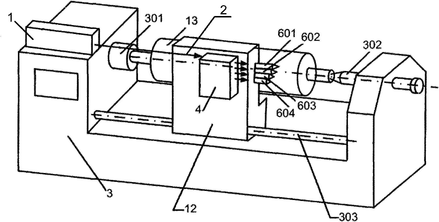
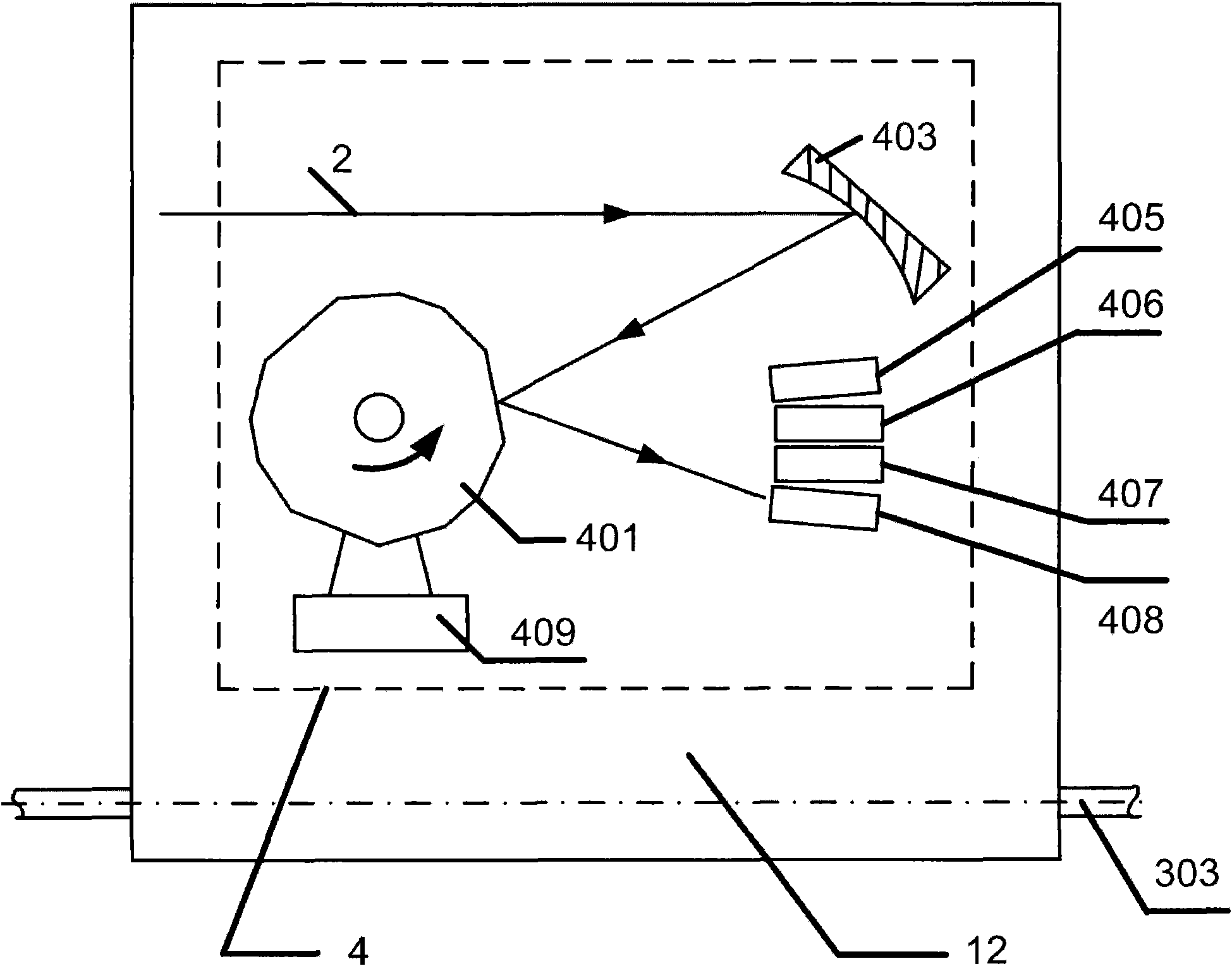
[0052] Embodiment 1: as figure 2 Shown is a specific embodiment of the present invention's focusing spot swing type laser roller type surface roughening processing device, which includes a laser 1 and a numerically controlled machine tool 3, and the said numerically controlled machine tool 3 adopts a conventional XL9 type numerically controlled machine tool. The working platform 12 driven by the translation guide rail 303 and the roll shaft 301 and the top 302 for installing the roll 13 are installed, and the roll shaft 301 and the top 302 are parallel to the translation guide rail 303 . The multi-prism scanning mechanism 4 and the integrated focus mechanism are housed on the described working platform 12, and the integrated focus mechanism consists of K=4 integrated focus heads (respectively the first integrated focus head 601, the second integrated focus head 602, the third integrated focus head 603 and the fourth integrated focusing head 604); and the laser 1 adopts high-p...

Embodiment 2

[0062] Embodiment 2: as figure 2 As shown, the surface roughening processing device of this focused light point swing type laser roller type provided by the present embodiment, its external structure is the same as that of embodiment 1, and the difference is that the first reflection in the polygon mirror scanning mechanism 4 of embodiment 1 The transmissive focusing lens 403 is replaced by the first transmissive focusing lens 404, and the internal structures of the four integrated focusing heads 601, 602, 603, 604 are all redesigned. Specifically taking the first integrated focusing head 601 as an example, in this embodiment, a second transmissive focusing mirror 7 and N=3 closely arranged focusing mirrors 901, 902 arranged opposite to the second transmissive focusing mirror 7 are provided in the present embodiment. , 903, such as Figure 8 as shown ( Figure 8 The high-speed motor 409 connected to one side of the polygon mirror 401 and the four beam splitting heads 405, 4...

Embodiment 3

[0063] Embodiment 3: as figure 2 As shown, the surface roughening processing device of this focused light point swing type laser roller type provided by the present embodiment, its external structure is the same as that of embodiment 1, and the difference is that the first reflection in the polygon mirror scanning mechanism 4 of embodiment 1 The transmissive focusing lens 403 is replaced by the first transmissive focusing lens 404, and the internal structures of the four integrated focusing heads 601, 602, 603, 604 are all redesigned. Specifically taking the first integrated focusing head 601 as an example, the present embodiment is provided with a second parabolic reflective focusing mirror 5 and N=3 closely arranged focusing mirrors 901 arranged opposite to the second parabolic reflective focusing mirror 5 , 902, 903, such as Figure 9 as shown ( Figure 9 The high-speed motor 409 connected to one side of the polygon mirror 401 and the four beam splitting heads 405, 406, ...


PUM


Abstract

The invention discloses a swinging-focal spot laser roller surface texturing method, which is characterized in that: continuous laser beams output by a high-power continuous laser are focused on a certain working face of a prism which is rotating at a high speed and of which the included angles between the normal lines of the working faces and the prism axis are inconsistent; K paths of pulse laser beams which are transmitted in a direction vertical to the rotation direction of the prism and quickly swing are formed by the scanning and splitting of the prism; the K paths of pulse laser beams are focused by K integrated focusing heads to form K*N focal spots which swing quickly along the length direction of a rotating roller to texture the surface of the roller at the same time to form irregular textured spot distribution of alternately arranged K*N non-spiral scanning line-point matrixes on the surface of the roller, wherein K is more than or equal to 1, N is the number of the focal spots output by a single integrated focusing head correspondingly, and K*N is more than or equal to 2. When the roller processed by the method rolls a steel plate, scratches in the length direction of the steel plate are avoided, and the rolling quality of the steel plate is improved.

Description

technical field [0001] The invention belongs to the field of laser roughening treatment on the surface of rollers, and in particular relates to a method and device for roughening the surface of laser rollers with a focused light spot swinging type. Background technique [0002] Textured cold-rolled steel sheets with special surface morphology are widely used in manufacturing, especially in the automobile and home appliance industries. Textured cold-rolled steel sheets are rolled by rolls with textured surfaces. Therefore, the surface morphology of texturized rolls has a great influence on the process performance of deep drawing and coating of cold-rolled steel sheets. [0003] In order to ensure that the cold-rolled steel plate has excellent shape, deep drawability, elongation and coating performance, in the production process of cold-rolled thin steel plate, it is required to roughen the surface of the cold-rolled work roll to meet the user's requirements. Textured cold-ro...

Claims


Application Information

Patent Timeline
Patent Type & Authority Applications(China)
IPC IPC(8): B23K26/00G02B26/12B23K26/046B23K26/064B23K26/067B23K26/359
Inventor 陈培锋王焄孙长东罗曦
Owner 苏州市博海激光科技有限公司
Why Eureka
Try Eureka