Method for molding vertical wall of deep foundation pit

A forming method and deep foundation pit technology, which can be applied in excavation, foundation structure engineering, blasting, etc., can solve problems such as the inability to construct the foundation of the factory building, affect the promotion of construction technology, and the instability of the foundation pit structure, so as to achieve good comprehensive benefits and good promotion The effect of low value and construction difficulty

Inactive Publication Date: 2011-07-27
CHONGQING IRON & STEEL (GRP) CO LTD
View PDF5 Cites 0 Cited by
  • Summary
  • Abstract
  • Description
  • Claims
  • Application Information

AI Technical Summary

Problems solved by technology

However, this method of mechanical grading and large excavation is mainly suitable for shallow soft soil foundation pits, and a large amount of rocks will be encountered in the excavation of ultra-deep foundation pits, so its construction is very difficult; During the excavation, it was necessary to divide into multiple steps and form a very long horse path, resulting in the excavation surface and excavation line reaching tens of meters, which had a serious impact on the construction of other nearby projects, making it impossible to construct the foundation of the factory building. At the same time, After pouring concrete on the pool wall, earthwork backfilling will also generate a very large lateral pressure on the pool wall structure. This additional load will cause the foundation pit structure to be unstable, and there are certain safety hazards
Not only that, considering the progress of the project and the analysis of the project cost, the method of grading and excavation not only takes a long time and has a large amount of work, but also costs a lot in excavation, transportation and backfilling. The project period is long and economical. The unfavorable factors of high cost also directly affect the promotion of construction technology

Method used


Image

  • Method for molding vertical wall of deep foundation pit
  • Method for molding vertical wall of deep foundation pit
  • Method for molding vertical wall of deep foundation pit

Examples


Embodiment Construction

[0018] The present invention will be further described below with reference to the drawings and specific embodiments.

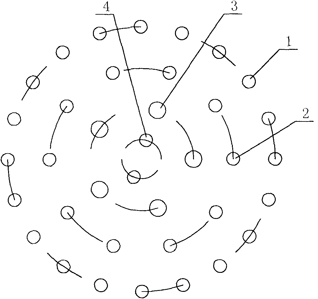
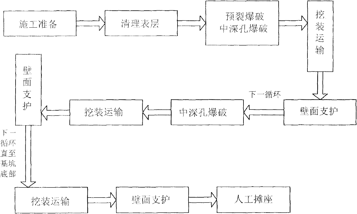
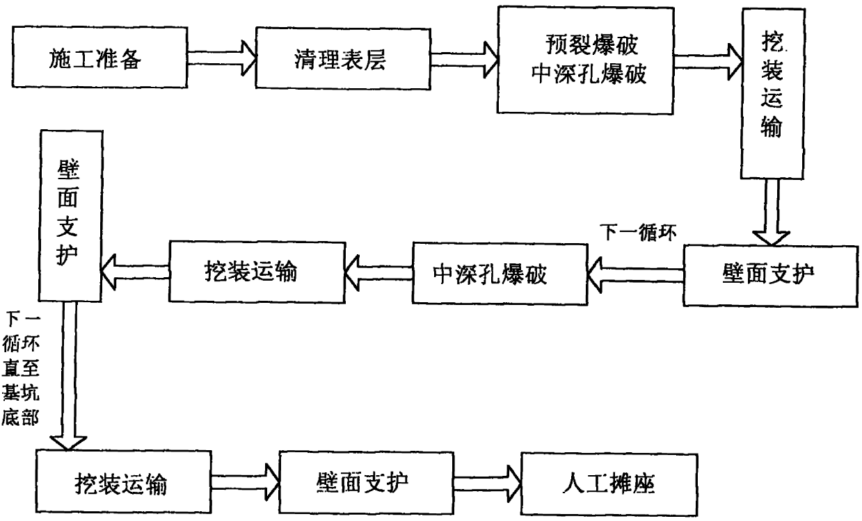
[0019] Such as figure 1 with figure 2 As shown, a method for forming a straight wall of a deep foundation pit is based on the shape characteristics and requirements of the foundation pit, as well as the environmental restrictions on blasting engineering, and adopts controlled blasting with peripheral pre-splitting and central layered loosening, including the following steps: ( 1) Set pre-split holes 1: According to the design requirements, drill a number of pre-split holes 1 on the edge of the preset range of the foundation pit. The pre-split holes 1 are formed by one-time drilling at the full depth of the pit, and each pre-split hole is filled with explosives Coil and the detonating cord connected to the explosive coil, the detonating cord is connected to the instantaneous detonator outside the hole, the pre-split hole adopts uncoupled charge, the non-coupling...


PUM


Abstract

The invention discloses a method for molding a vertical wall of a deep foundation pit. The method comprises the following steps: drilling a plurality of presplit holes on a preset edge of the foundation pit and filling each presplit hole with a stick dynamite and a detonating fuse connected with an instant electric detonator outside the hole by adopting full-pit-depth one-step drilling molding; forming a buffer hole, a main explosion hole and a cutting hole in turn from outside to inside on the surface layer of the foundation pit; arranging segmented stick dynamites and non-electric millisecond difference detonators in the buffer hole, the main explosion hole and the cutting hole, wherein the non-electric millisecond difference detonators are connected with the instant electric detonators; after all the instant electric detonators are connected with each other in series, connecting all the instant electric detonators to a trigger; igniting a plurality of rows of blast holes at the same time and detonating the presplit hole, the cutting hole, the main explosion hole and the buffer hole in turn; after blasting, performing digging and transportation and wall surface timbering in sequence; blasting step by step to the bottom of a preset foundation pit; and manually repairing and scattering the bottom of the foundation pit. The method has the advantages of little construction difficulty, high protection safety, short construction period, stable engineering project quality and excellent comprehensive benefit.

Description

Technical field [0001] The present invention relates to earth and rock excavation and blasting technology, in particular to ultra-deep foundation pit excavation technology under relatively complicated geological conditions such as mudstone, sandstone, etc., in particular to a deep foundation pit for making a swirling pool of a steelmaking water treatment system Straight wall molding method. Background technique [0002] In construction projects, foundation pit excavation projects are often encountered. In view of different engineering geological conditions, such as rock structures composed of mudstone and sandstone, earth and stone excavation and blasting techniques are often used in foundation pit excavation, especially in When excavating deep pools or deep pits with a diameter and depth of several tens of meters, due to the staggered distribution of rocks, it is very difficult to use mechanical methods to break and excavate, and the technical and safety requirements of blasting...

Claims


Application Information

Patent Timeline
Patent Type & Authority Patents(China)
IPC IPC(8): E02D17/02E02D19/20F42D3/04
Inventor 姜元庆杨曙东罗欣
Owner CHONGQING IRON & STEEL (GRP) CO LTD
Why Eureka
Try Eureka