
Waste heat recovery system of petrochemical heating furnace

A waste heat recovery system and petrochemical technology, applied in the field of petrochemical industry, can solve the problems of single replacement, low efficiency of heating furnace, easy dust accumulation, etc., and achieve the effect of increasing flexibility, improving thermal efficiency and protecting equipment

Inactive Publication Date: 2010-08-25
CHINA PETROCHEMICAL CORP +1
View PDF0 Cites 20 Cited by
  • Summary
  • Abstract
  • Description
  • Claims
  • Application Information

AI Technical Summary

Problems solved by technology

The plate air preheater has no limit on the maximum flue gas temperature, but due to the small gap between the plates, it is easy to accumulate dust under the condition of insufficient combustion
The sealing structure between the plates determines that it cannot be replaced individually like a heat pipe air preheater, but can only be replaced by a whole group of plates
The petrochemical heating furnace waste heat recovery system is usually equipped with a one-stage air preheater. The problem is that once dew point corrosion occurs in the low temperature area inside the air preheater, it can only be removed from the waste heat recovery system as a whole for maintenance and replacement. Change to the natural ventilation operation state, so that the heating furnace will operate at low efficiency during the whole preheater maintenance and replacement process, which is obviously very energy-consuming and uneconomical

Method used


Image

  • Waste heat recovery system of petrochemical heating furnace
  • Waste heat recovery system of petrochemical heating furnace
  • Waste heat recovery system of petrochemical heating furnace

Examples


Embodiment Construction

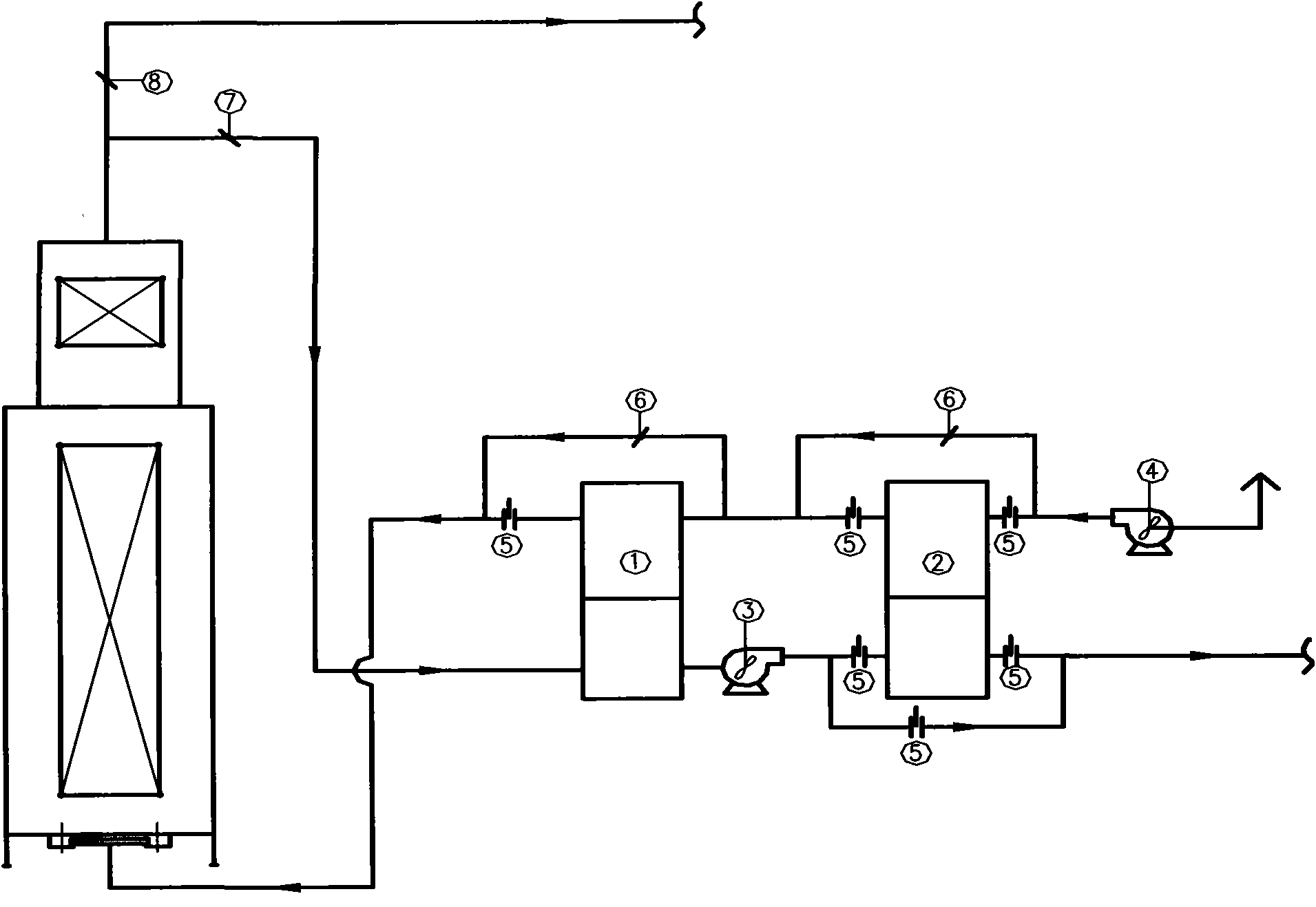
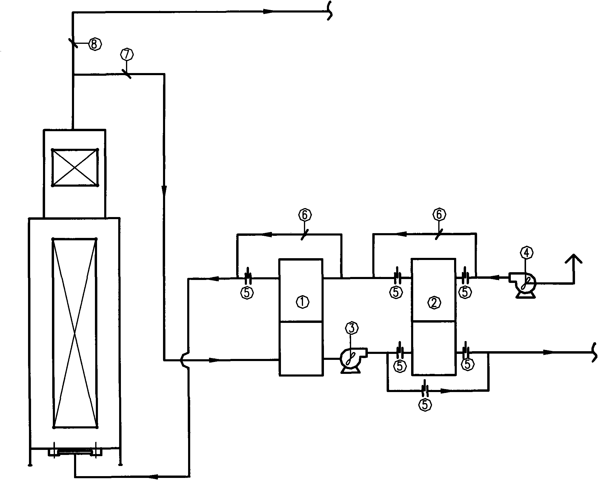
[0022] As shown in Fig. 2, a petrochemical heating furnace waste heat recovery system includes an air preheater, an induced draft fan 3, and a blower fan 4.

[0023] In order to adapt to different working conditions, the air preheater includes a high temperature section air preheater 1 and a low temperature section air preheater 2 . Specifically, the flue gas outlet temperature of the air preheater 1 in the high temperature section is 160-170 degrees, and a tubular or heat pipe or plate air preheater is adopted; the flue gas of the air preheater 2 in the low temperature section The outlet temperature is equal to or lower than 100 degrees, using plate or cast iron plate tube or glass tube or enamel tube.

[0024] The induced draft fan 3 is arranged between the air preheater 1 of the high temperature section and the air preheater 2 of the low temperature section, so that the induced draft fan 3 can be kept running at a temperature above the dew point for a long time, thereby ens...


PUM


Abstract

The invention relates to a waste heat recovery system of a petrochemical heating furnace and belongs to the technical field of petrochemistry. The device comprises a high-temperature section air preheater, a low-temperature section air preheater, a blower, a draught fan arranged between the high-temperature section air preheater and the low-temperature section air preheater, two bypass air ducts, a bypass flue, a gate valve and two baffle plates, wherein one bypass air duct, the bypass flue, the gate valve and one baffle plate are arranged in a low-temperature section; and one bypass air duct and one baffle plate are arranged in the high-temperature section. The system improves the heating efficiency of the heating furnace, makes the draught fan operate at a temperature above a dew point all the time and prevents the impeller of the draught fan from low-temperature corrosion. In addition, when having serious wind leakage or blockage due to low temperature fume corrosion, the low-temperature section air preheater can be cut off manually while the heating furnace still operates with 90 percent efficiency, so the normal operation of the heating furnace and the high-temperature section air preheater is not affected and the low-temperature corrosion of the high-temperature section is avoided.

Description

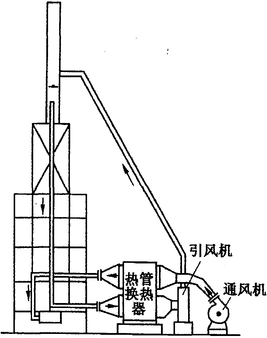
technical field [0001] The invention belongs to the field of petrochemical industry, and in particular relates to a petrochemical heating furnace waste heat recovery system. Background technique [0002] In petrochemical plants, in order to improve the thermal efficiency of the heating furnace, it is usually necessary to set up a flue gas waste heat recovery system. In the flue gas waste heat recovery system, the air preheater is generally used to realize the heat exchange between the hot flue gas and the cold air, so as to reduce the exhaust gas temperature of the heating furnace and improve the thermal efficiency. Air preheaters include thermal oil type, rotary type, steel tube type, glass tube type, heat pipe type, plate type, etc. Compared with tubular and rotary air preheaters, the heat pipe air preheater has the advantages of small size, light weight, and high efficiency. It was widely used in the domestic petrochemical industry in the 1970s and was quickly promoted. ...

Claims


Application Information

Patent Timeline
IPC IPC(8): F27D17/00F23L15/00
CPCY02E20/34Y02P10/25
Inventor 厉亚宁赵建国李文辉冯永生
Owner CHINA PETROCHEMICAL CORP
Learn More