

Stator double-armature winding air-cored pulse generator and method thereof for realizing pulse discharge
A double armature winding and armature winding technology, applied in the shape/style/structure of winding conductors, electrical components, electromechanical devices, etc., to achieve the effects of compact structure, high power density and small volume
- Summary
- Abstract
- Description
- Claims
- Application Information
AI Technical Summary
Problems solved by technology
Method used
Image

Examples
specific Embodiment approach 1
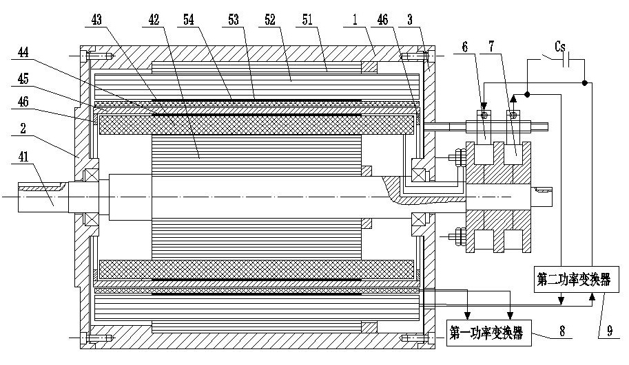
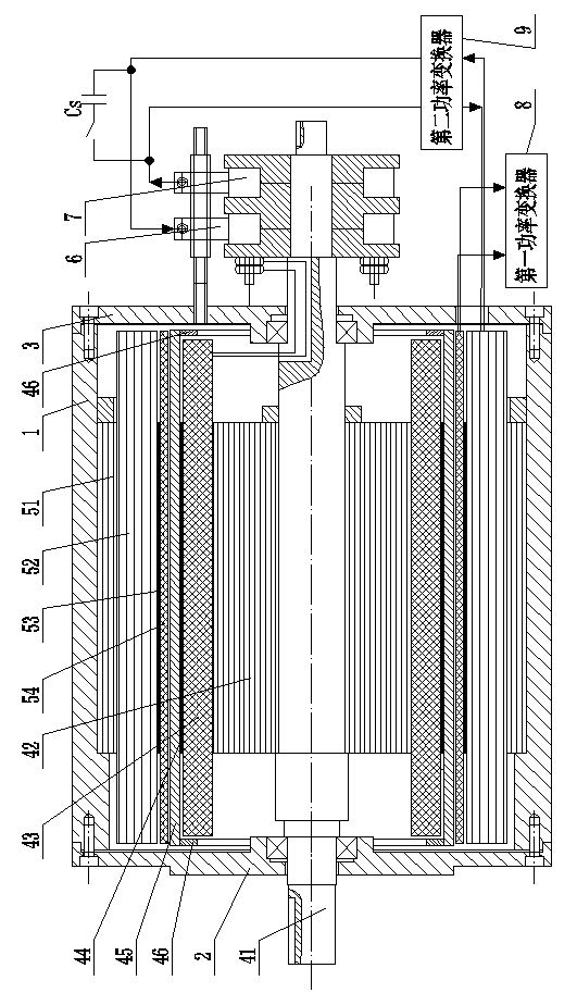
[0022] Specific Embodiment 1: The present embodiment will be described below in conjunction with Fig. 1 and Fig. 2. The motor described in the present embodiment is a rotating electric machine, which consists of a casing 1, a front end cover 2, a rear end cover 3, a hollow rotor, a hollow stator, Composed of brushes 6 and slip rings 7, the axes of the hollow rotor and the hollow stator coincide,
[0023] The air-core rotor includes a rotor main shaft 41, an annular rotor glass fiber epoxy resin yoke 42, a slotless field winding 43, a carbon fiber epoxy resin bandage 44 and an aluminum compensation cylinder 45;
[0024] The hollow core stator includes an annular stator glass fiber epoxy resin yoke 51, a secondary armature winding 52, a glass fiber epoxy resin bandage 53 and a main armature winding 54, the secondary armature winding 52 and the main armature winding 54 are both single Phase slotless winding;
[0025] The ring-shaped stator glass fiber epoxy yoke 51, the secondar...
specific Embodiment approach 2
[0032] Embodiment 2: The difference between this embodiment and Embodiment 1 is that the slotless excitation winding 43 and the carbon fiber epoxy resin bandage 44 are bonded and fixed by an epoxy resin layer, and the carbon fiber epoxy resin bandage 44 and the aluminum The compensation cylinders 45 are bonded and fixed by epoxy resin layers. Other components and connections are the same as those in Embodiment 1.
[0033] The carbon fiber epoxy resin bandage 44 cannot withstand the high temperature of the traditional shrink-fitting process. A certain thickness of epoxy resin layer is poured between the aluminum compensation cylinder 45 and the carbon fiber epoxy resin bandage 44, which can ensure that the aluminum compensation cylinder 45 and the carbon fiber epoxy resin bandage 44 are not loose, and the safe thickness of the epoxy resin layer can be obtained through theoretical calculation; the slotless excitation winding 43 and the carbon fiber epoxy resin bandage 44 are bon...
specific Embodiment approach 3
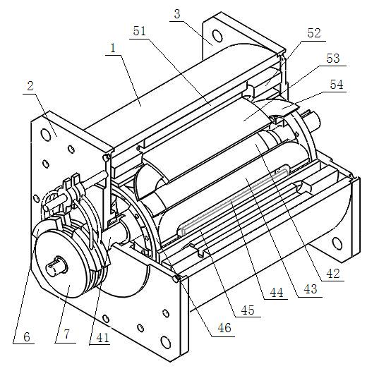
[0034] Specific Embodiment Three: The present embodiment will be described below with reference to FIG. 2 . The difference between this embodiment and Embodiment 1 is that the hollow rotor further includes two counterweight rings 46 , and the inner ring surface of the aluminum compensation cylinder 45 A counterweight ring 46 is respectively fixed at both ends. Other components and connections are the same as those in Embodiment 1.
[0035] The setting of the counterweight ring 46 is used to adjust the dynamic balance of the air-core rotor on the one hand when the air-core rotor rotates at high speed, and on the other hand to make the aluminum compensation cylinder 45 loose from the annular rotor glass fiber epoxy resin yoke 42. reduce. In order to further strengthen the effect, configuration blocks can also be set on the counterweight ring 46 .
PUM
 Abstract
Description
Claims
Application Information