Intake and exhaust systems for supercharged internal combustion engine
A technology of air intake system and exhaust system, applied in the direction of fuel air intake, internal combustion piston engine, exhaust device, etc., can solve the problems of compressor surge, sudden change of intake pressure of diesel engine, low boosting efficiency, etc. Achieve the effect of increasing flow and avoiding surge
- Summary
- Abstract
- Description
- Claims
- Application Information
AI Technical Summary
Problems solved by technology
Method used
Image
Examples
Embodiment 1
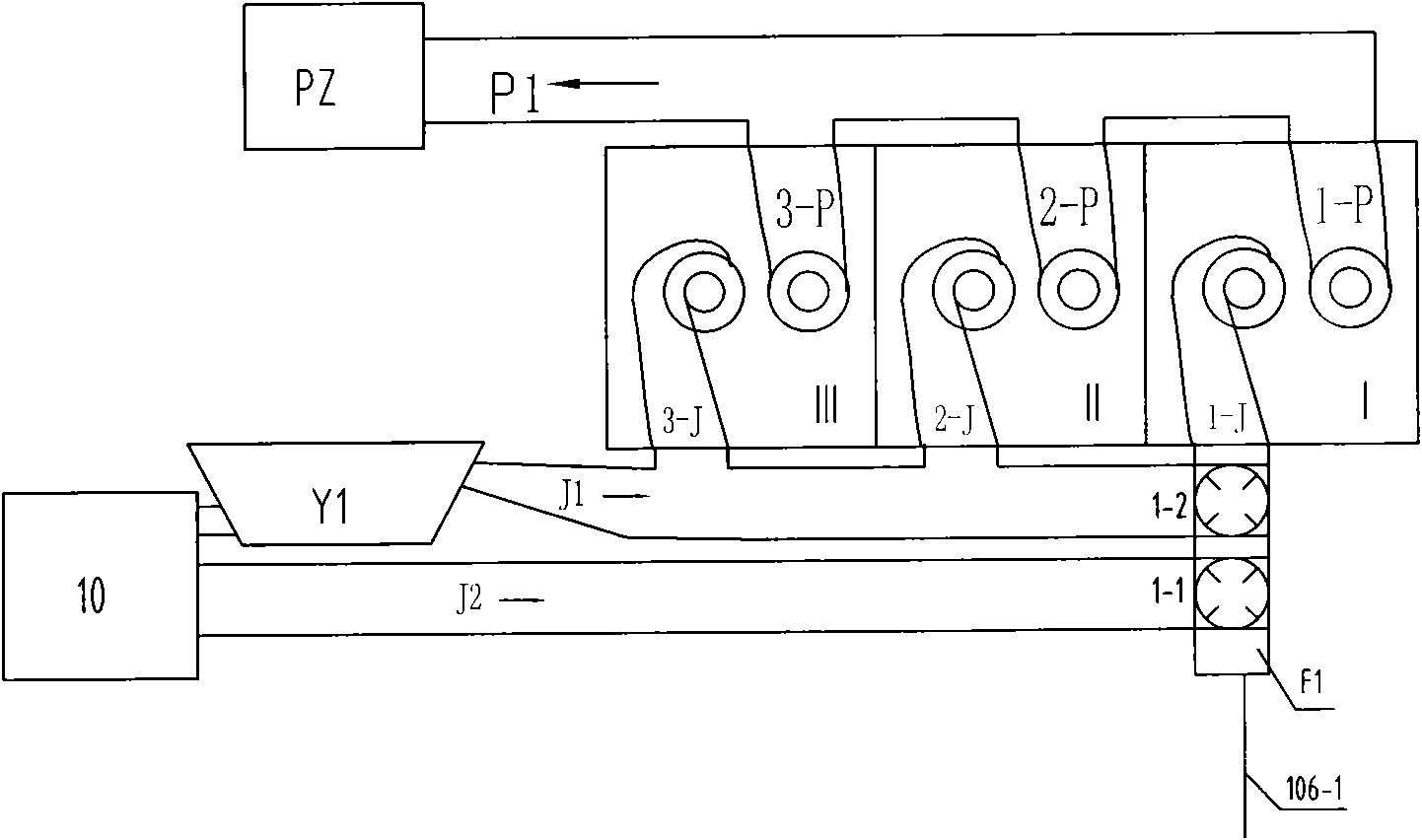
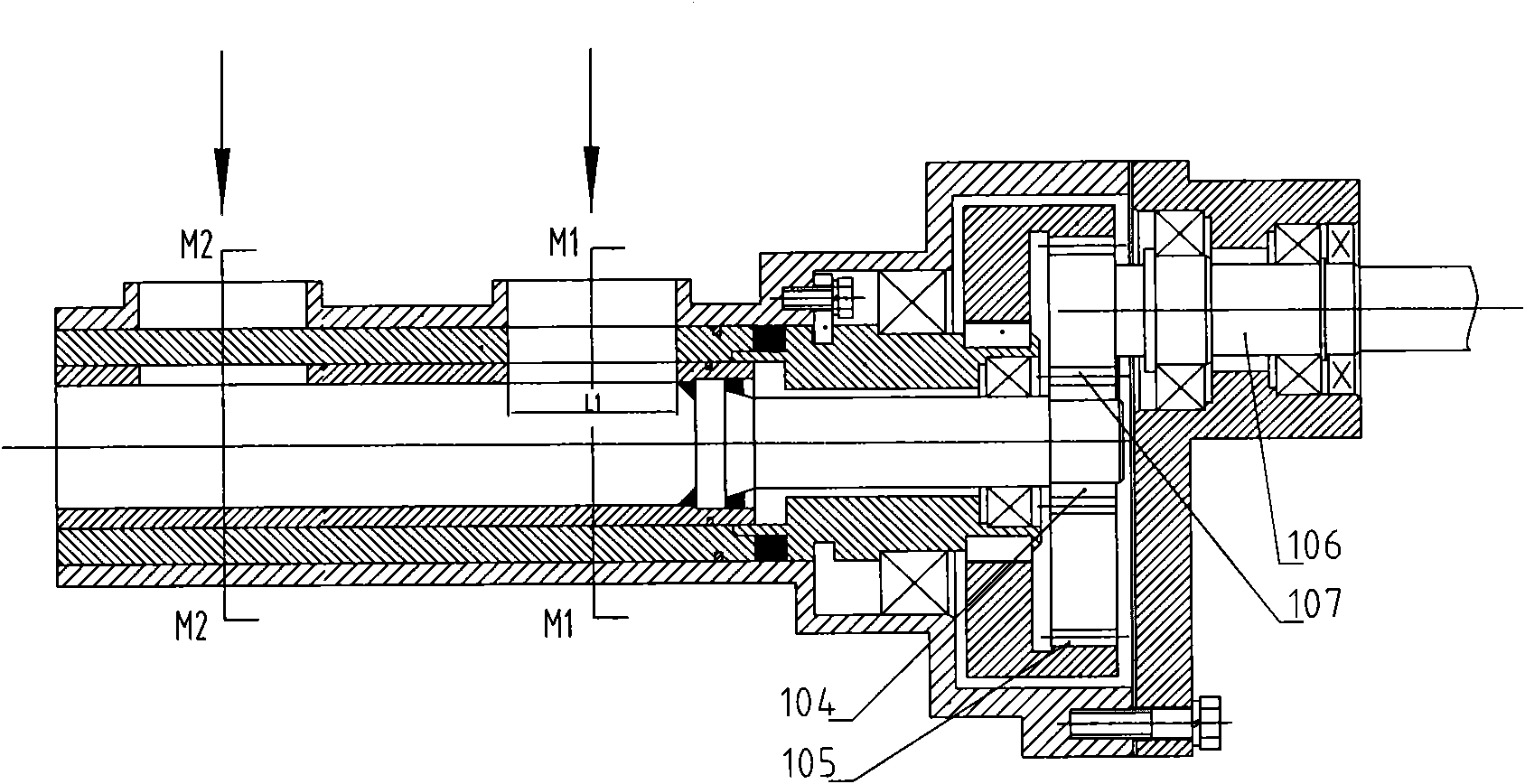
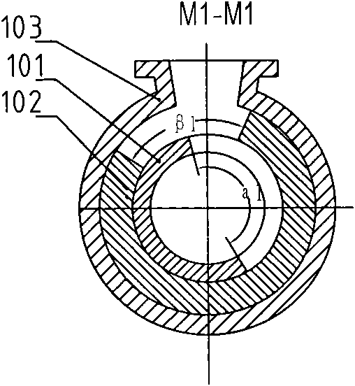
[0040] Such as figure 1 , is a four-stroke three-cylinder (corresponding cylinder number is I-III) mechanically supercharged intake and exhaust system, the intake system includes: 2 intake pipes J1, J2, and a compressor Y1 of a supercharger; The inlet of the compressor Y1 is connected to the air filter 10, the outlet of the compressor Y1 is connected to the inlet of the intake pipe J1; the inlet of the intake pipe J2 is directly connected to the air filter 10; the two intake pipes J1, J2 are connected to the intake There is one air intake auxiliary control valve F1 between the channels 1-J; the air intake pipe J1 is directly connected with the air intake channels 2-J and 3-J; the air intake auxiliary control valve F1 of the air intake channel 1-J The opening and closing correspond to the phase of the gas distribution timing of the intake valve of the first cylinder of the internal combustion engine, so that the complete intake process of the intake port 1-J is divided into two...
Embodiment 2
[0048] Such as Figure 6 , an optimized intake and exhaust system for a four-stroke six-cylinder (corresponding to cylinder number I-VI) turbocharged internal combustion engine, the intake system includes: 2 intake pipes J1, J2, a turbocharger compressor Y1 (to form a turbocharger with the turbine W1 of the exhaust system); the inlet of the compressor Y1 is connected to the air filter 10, the outlet of the compressor Y1 is directly connected to the inlet of the intake pipe J1; the inlet of the intake pipe J2 is directly connected to the The air filter 10 is connected; there is an intercooler Z1 (cooling the supercharged air) in the pipeline of the air intake pipe J1; two air intake pipes are respectively arranged between the two air intake pipes J1, J2 and each air inlet. Air-assisted control valves F1, F2; the opening and closing of the air-intake auxiliary control valves connected to the six intake ports 1-J, 2-J, 3-J, 4-J, 5-J, and 6-J correspond to the internal combustion ...
Embodiment 3
[0064] Such as Figure 12 , is an optimized intake and exhaust system for a four-stroke six-cylinder (corresponding to cylinder number I-VI) turbocharged + supercharged internal combustion engine. The intake system includes: 2 intake pipes J1, J2, a turbocharger The compressor Y1 of the exhaust system (which forms a turbocharger with the turbine W1 of the exhaust system) and an electric compressor Y2; there are two intake auxiliary control valves between the two intake pipes J1, J2 and each intake port Valves F1, F2; the inlet of compressor Y1 is connected with air filter 10, the outlet of compressor Y1 is directly connected with the inlet of intake pipe J1; the inlet pipe J1 has two outlets, one outlet is connected with the inlet of auxiliary control valve F1 , the other outlet is connected to the inlet of compressor Y2 through the low-speed flow control valve F10; the outlet of compressor Y2 is directly connected to the inlet of the intake pipe J2; the outlet of the intake p...
PUM
 Abstract
Description
Claims
Application Information
 - R&D
- Intellectual Property
- Life Sciences
- Materials
- Tech Scout
- Unparalleled Data Quality
- Higher Quality Content
- 60% Fewer Hallucinations
Browse by: Latest US Patents, China's latest patents, Technical Efficacy Thesaurus, Application Domain, Technology Topic, Popular Technical Reports.
© 2025 PatSnap. All rights reserved.Legal|Privacy policy|Modern Slavery Act Transparency Statement|Sitemap|About US| Contact US: help@patsnap.com


