
Distributed optical fiber Raman temperature sensor coding and decoding by adopting sequential pulse

A distributed optical fiber and temperature sensor technology, applied in the direction of physical/chemical change thermometers, thermometers, instruments, etc., can solve the problems of reducing the real-time response ability of temperature measurement, increasing the working time of the system, and difficult temperature demodulation, etc. The effect of increasing the intensity of Raman scattered light, preventing the nonlinear effect of fiber optics, and reducing the spatial resolution

Inactive Publication Date: 2010-09-01
CHINA JILIANG UNIV
View PDF5 Cites 27 Cited by
  • Summary
  • Abstract
  • Description
  • Claims
  • Application Information

AI Technical Summary

Problems solved by technology

In order to solve this problem, the traditional method is to increase the emission power of narrow laser pulses, but after increasing the emission power to a certain extent, Raman scattered light will have nonlinear effects, making temperature demodulation extremely difficult
Another way is to increase the number of signal acquisitions and improve the signal-to-noise ratio by averaging multiple times, but this increases the working time of the system, thereby reducing the real-time response capability of temperature measurement

Method used


Image

  • Distributed optical fiber Raman temperature sensor coding and decoding by adopting sequential pulse
  • Distributed optical fiber Raman temperature sensor coding and decoding by adopting sequential pulse
  • Distributed optical fiber Raman temperature sensor coding and decoding by adopting sequential pulse

Examples


Embodiment Construction

[0012] Further illustrate the present invention below in conjunction with accompanying drawing.

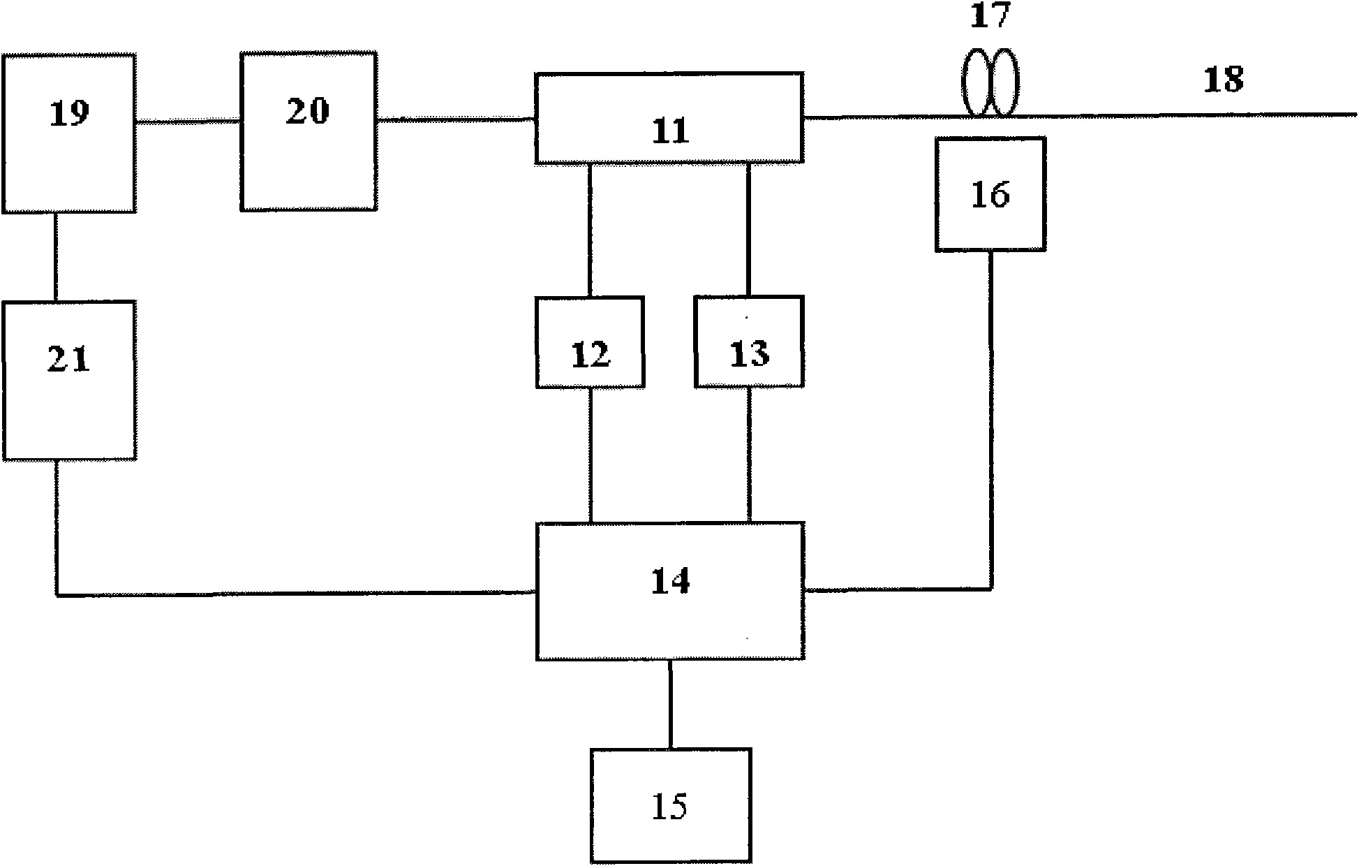
[0013] refer to figure 1 , the distributed optical fiber Raman temperature sensor adopting sequence pulse code decoding of the present invention comprises the fiber-coupled multi-pulse semiconductor laser emitting module 21 with Raman frequency shift, the erbium-doped optical fiber amplifier 19, the bandpass filter 20, has four An integrated optical fiber wavelength division multiplexer 11 with two ports, two photoelectric receiving and amplifying modules 12, 13, a codec and demodulation digital signal processor 14, an optical fiber temperature sampling loop 17, an intrinsic temperature measuring optical fiber 18, and a digital temperature Detector 16 and PC 15. The output end of the fiber-coupled multi-pulse semiconductor laser emitting module 21 is connected to the input end of the erbium-doped fiber amplifier 19, and the output end of the erbium-doped fiber amplifier 19 is con...


PUM

PropertyMeasurementUnit
Center wavelengthaaaaaaaaaa

Abstract

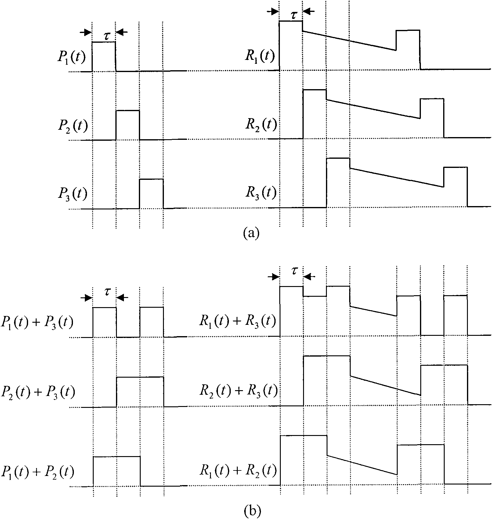
The invention discloses a distributed optical fiber Raman temperature sensor coding and decoding by adopting sequential pulses, which is a distributed optical fiber temperature measuring system coding and decoding a signal on the basis of S-matrix transformation and carrying out optical fiber on-line positioning temperature measurement by utilizing the effect of optical fiber Raman light intensity modulated by temperature and an optical time domain reflection principle. The distributed optical fiber Raman temperature sensor can obtain better signal-to-noise radio under the condition of spending same measuring time by using a sequential multidigit laser pulse coding and decoding technology, increase the number of emitted photons, enhance the space resolution by narrowing the thicknesses of laser pulses and also effectively prevent the nonlinear effect of optical fibers by lowering the requirements on the peak value power of a single laser pulse; and in addition, the invention effectively solves the contradiction of space resolution enhancement-signal-to-noise radio reduction and signal-to-noise radio enhancement-space resolution reduction or measuring time increase of the traditional optical fiber distribution temperature sensor, enhances the temperature measuring precision, can be used for a distributed optical fiber temperature sensor which has ultra long range and high space resolution.

Description

technical field [0001] The invention relates to an optical fiber temperature sensor, especially a distributed optical fiber Raman temperature sensor. Background technique [0002] Distributed optical fiber temperature sensor system is a sensor system for real-time measurement of spatial temperature field distribution. In the system, optical fiber is both a transmission medium and a sensing medium. The distributed optical fiber Raman temperature sensor uses the Raman spectrum effect of the optical fiber. The temperature field of each point in the space where the optical fiber is located modulates the optical carrier transmitted in the optical fiber. After demodulation, the information of the spatial temperature field is displayed in real time. It is a special optical fiber communication system; using optical time domain reflection (OTDR) technology of optical fiber, the measured temperature point is located by the propagation speed of light in the optical fiber and the time o...

Claims


Application Information

Patent Timeline
IPC IPC(8): G01K11/32G01K11/324
Inventor 余向东张在宣张文生
Owner CHINA JILIANG UNIV
Learn More