Motor with strong weak air-gap field in alternative distribution

An air-gap magnetic field, strong and weak technology, used in motors, electric vehicles, magnetic circuit shape/style/structure, etc., can solve problems such as out-of-step, locked rotor, large torque ripple, etc.

Inactive Publication Date: 2010-09-01
王铂仕
View PDF0 Cites 18 Cited by
  • Summary
  • Abstract
  • Description
  • Claims
  • Application Information

AI Technical Summary

Problems solved by technology

For example: Although the AC asynchronous motor has the advantages of simple structure, reliable operation, long life, low cost and easy maintenance, compared with the DC motor, it has poor speed regulation performance, small starting torque, low overload capacity and efficiency, and its The generation of the rotating magnetic field needs to absorb reactive power from the grid, so the power factor is low, and a large amount of electric energy is virtually lost
Although synchronous motors have high working efficiency, low noise, and small torque fluctuations, they are difficult to start and prone to out-of-step and stalled problems.
Switched reluctance motors have simple structure, reliable operation, good starting performance, and good speed regulation performance, but have the defects of large torque ripple, high noise, an

Method used


Image

  • Motor with strong weak air-gap field in alternative distribution
  • Motor with strong weak air-gap field in alternative distribution
  • Motor with strong weak air-gap field in alternative distribution

Examples


Embodiment 1

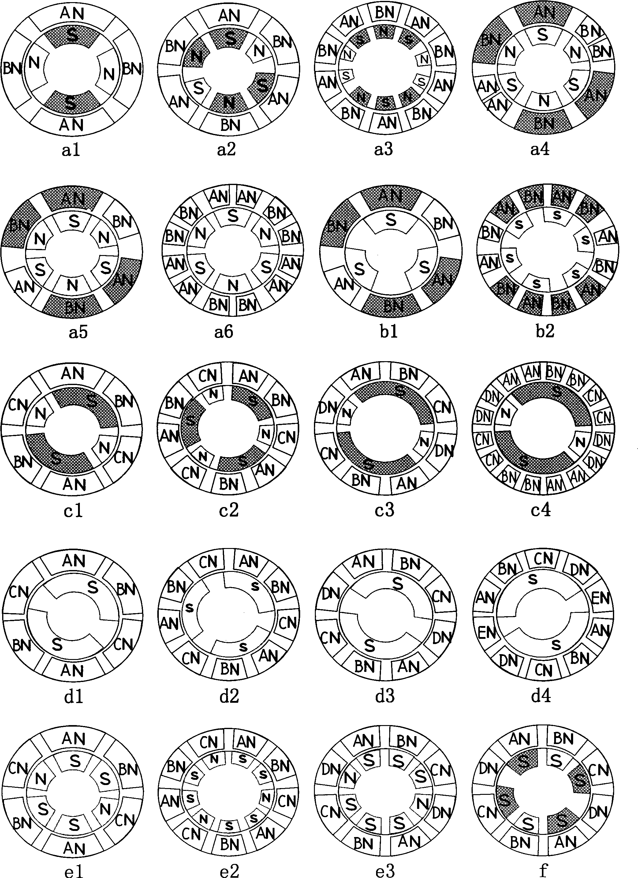
[0092]Embodiment 1: As shown in Figure 10a1, it is a four-pole permanent magnet stable pole magnet rotor equipped with a four-phase eight-pole pole-changing magnet stator with a position sensor DC commutation motor. The motor has four sensors H1-H4 to detect the rotor position The signal controls the four NPN triode switches of VT1-VT4 respectively, and the triode switches are respectively connected to the four-phase windings of A, B, C and D. As shown in the figure, H1 senses the rotor pole N, there is no signal output, VT1 is cut off, the A-phase winding is powered off, and loses its attraction to the rotor pole S; H4 senses the rotor pole S, outputs a positive signal, VT4 conducts, D The phase winding is energized, so that the stator magnetic pole DN generates a repulsive force to the rotor magnetic pole N (and part of the magnetic force line of DN passes through AN to make AN have S polarity, which generates a repulsive force to the rotor magnetic pole S, and the following ...

Embodiment 2

[0093] Embodiment 2: As shown in Figure 10a2, it is a position sensorless DC commutation motor with a four-pole permanent magnet stable pole magnet rotor and a four-phase eight-pole variable pole magnet stator. Its working principle is basically the same as that of Embodiment 1, except that the electronic The control signal of the switch is generated by the rotor position sensor instead by four circuits with the same frequency timing pulse generation circuit. As shown in the figure, the four channels of the same frequency sequential pulse generator circuit output four channels of pulse signals with the same frequency and the same duty cycle in turn at equal intervals, and turn on and off the four NPN transistor switches of VT1-VT4 in turn. , and then turns on and off the A, B, C, D four-phase stator windings in turn to form a stator rotating magnetic field, so that the rotor continues to rotate. At the same time, the motor is equipped with a mechanical forward switch. When the...

Embodiment 3

[0094] Embodiment 3: As shown in Figure 10a3, it is a sensorless AC commutation motor with an eight-pole permanent magnet stable pole magnet rotor and a two-phase eight-pole pole-changing magnet stator. Two diodes connect the two-phase stator windings to the unidirectional AC power supply respectively. As shown in the figure, when the power supply is in the positive half cycle, the current is given by Flow through VD1, A winding, VD4 Make the stator magnetic pole AN and the rotor magnetic pole S attract each other; when the power supply is in the negative half cycle, the current is from Flow through VD2, B winding, VD3 Make the stator magnetic pole BN and the rotor magnetic pole N repel each other, because the rotor magnet corresponding to the small magnet of the stator is on the clockwise side, the rotor rotates clockwise, and then the stator magnetic pole BN and the rotor magnetic pole S attract each other until the center of the magnetic pole is aligned; when the powe...


PUM


Abstract

The invention provides a motor which has low cost, saves energy, has high efficiency, is self-starting, has no blocking, is not asynchronous and has no torque pulsation, wide application range and strong weak air-gap field in alternative distribution. The motor is designed based on the principle that like poles repel and unlike poles attract in magnetic field, the stator (or rotor) adopts magnets which are in the same size and in uniform distribution, and the corresponding rotor (or stator) adopts magnets which are not in the same size, wherein small magnets deflect the same polar distance in the same direction, or the corresponding rotor (stator) adopts magnets which are in the same size, wherein a small number of symmetrical magnets deflect the same polar distance in the same direction; or the stator and rotor all adopt magnets which are not in the same size, wherein small magnets deflect the same polar distance in the same direction; or the stator (or rotor) adopts electromagnets which are in the same size and in uniform distribution and windings of all phases are on and off in turn, and the corresponding rotor (or stator) adopts magnet which does not deflect. The strong weak air-gap magnetic field in alternative distribution along circumference 'strong weak strong weak......, strong strong weak strong strong weak......, strong strong strong weak strong strong strong weak.......' is formed between the stator and rotor, thus the motor can be self-starting and can operate stably.

Description

technical field [0001] The invention relates to a rotating electric machine which can be used not only as a generator but also as a motor. When used as a generator, it can be used as an AC generator or a DC generator; when used as a motor, it can be used as an AC motor or a DC motor. Background technique [0002] A rotating electrical machine is an electromechanical energy conversion device manufactured based on magnetic energy to generate electricity and electric energy to generate magnetism. There are many types of modern motor products and are widely used, but there are more or less defects in the existing motors. For example: Although the AC asynchronous motor has the advantages of simple structure, reliable operation, long life, low cost and easy maintenance, compared with the DC motor, it has poor speed regulation performance, small starting torque, low overload capacity and efficiency, and its The generation of the rotating magnetic field needs to absorb reactive po...

Claims


Application Information

Patent Timeline
IPC IPC(8): H02K1/06
CPCY02T10/641Y02T10/64
Inventor 王铂仕
Owner 王铂仕
Why Eureka
Try Eureka