Method of making mounting mats for mounting pollution control element

A pollution control component and pollution control technology, applied in the direction of household components, engine components, applications, etc., can solve the problems of performance change, non-reproducibility, fiber length limitation, etc., and achieve the effect of high cost performance

Inactive Publication Date: 2010-09-01
3M INNOVATIVE PROPERTIES CO
View PDF23 Cites 13 Cited by
  • Summary
  • Abstract
  • Description
  • Claims
  • Application Information

AI Technical Summary

Problems solved by technology

For example, the fiber lengths that can be used on these machines are often limited
Additionally, adjuvants required during the formulation of the mounting mat may not be compatible with these machines, or their use may result in a mounting mat that does not meet the desired properties or may result in the creation of a mat that varies greatly in performance.
In addition, known dry-laid processes can be too aggressive, leading to undesired fiber breakage, irreproducible properties, dust formation, etc. during production

Method used


Image

  • Method of making mounting mats for mounting pollution control element
  • Method of making mounting mats for mounting pollution control element
  • Method of making mounting mats for mounting pollution control element

Examples


example 1

[0163] An intumescent mounting mat having the following composition was prepared (all numbers are in parts by weight):

[0164] 54.3% fiber ("ISOFRAX")

[0165] 13.6% chopped R-glass fibers, 6mm long, heat treated at 700°C for 1 hour

[0166] 29.2% unexpanded vermiculite

[0167] 2.9% bicomponent fiber ("TREVIRA 255")

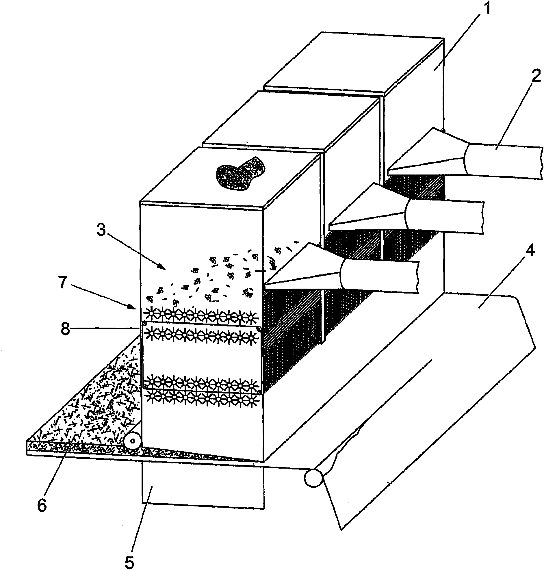
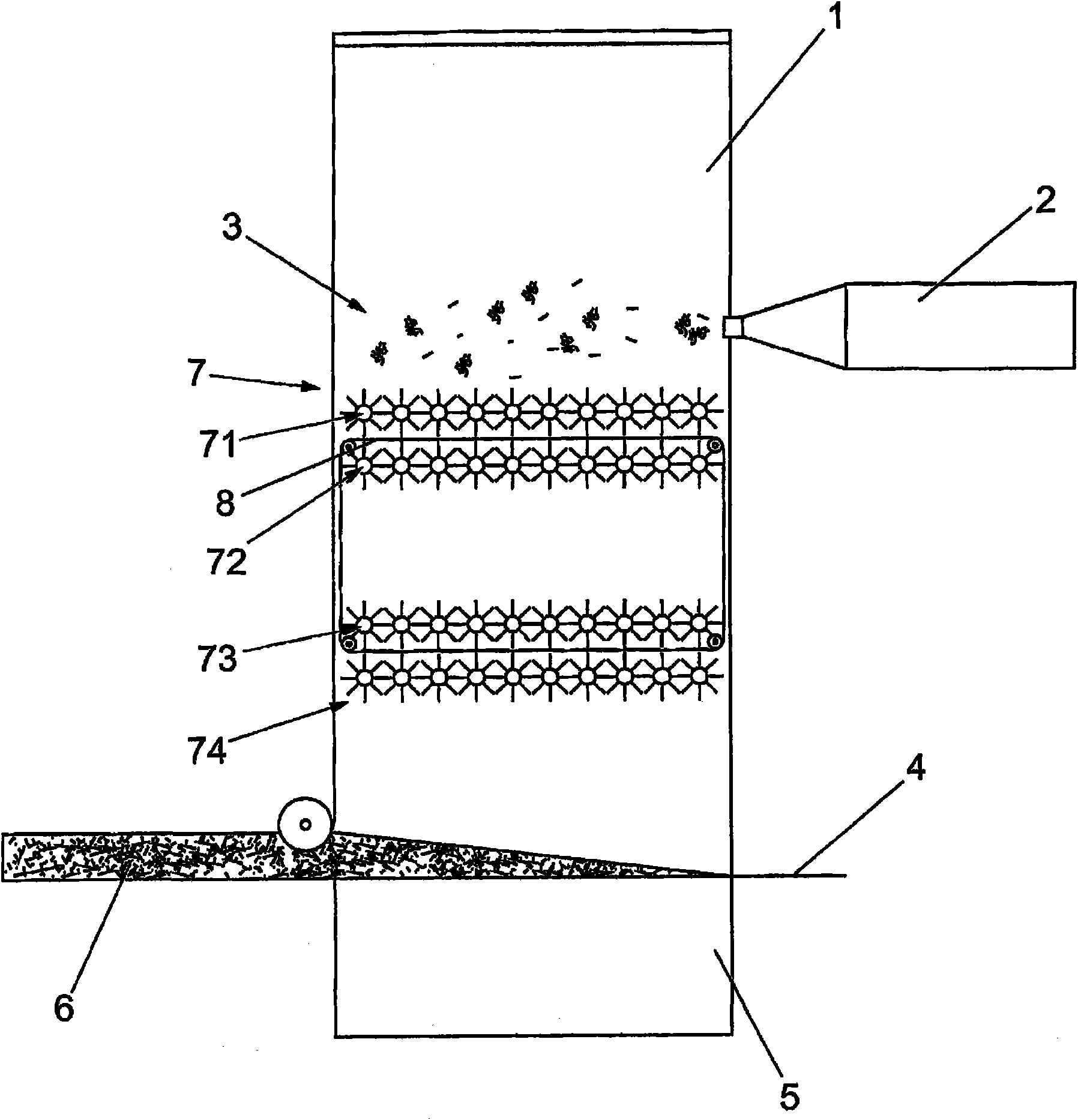
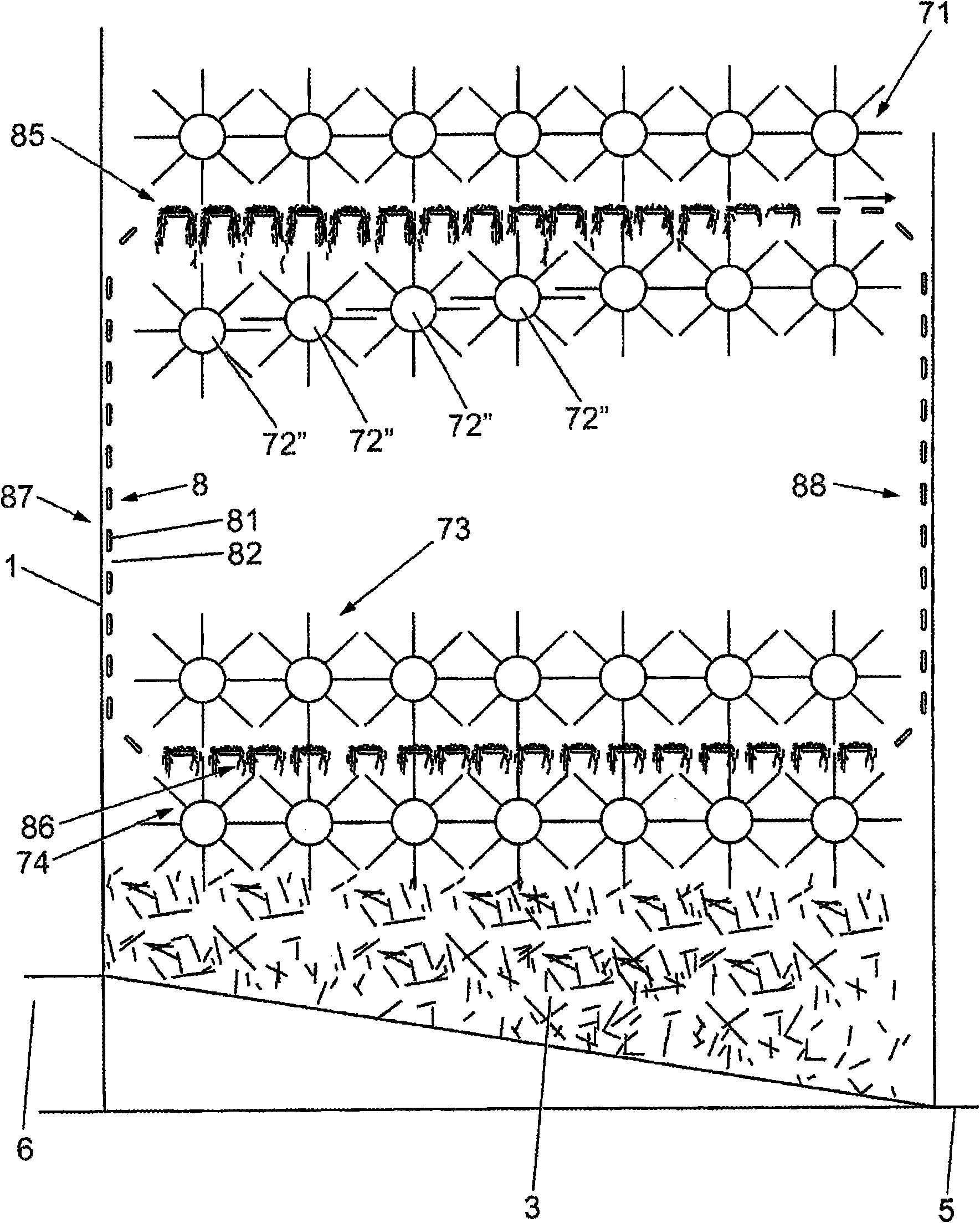
[0168] The intumescent mounting mat of Example 1 was prepared on a 310 nm wide nonwoven machine commercially available from Formfiber (Denmark) and operated according to the method disclosed above. The forming box of this machine basically corresponds to figure 2 The schematic diagram shown, whereby the forming box has two rows of three toothed rollers arranged opposite to each other on the upper part of the forming box and two rows of three toothed rollers arranged opposite to each other near the bottom of the forming box. Such as figure 2 As shown, the endless belt screen runs between the upper toothed roller row and the lower toothed roller row. The fo...

example 2

[0187] A non-intumescent mounting mat having the following composition was prepared in the same manner as described in Example 1, except that, after the oven, the mat was compressed with rollers in such a way that after cooling, the initially formed thickness of about 45 mm was reduced. As small as about 13mm (all numbers are by weight):

[0188] 32.4% fiber ("SUPERWOOL 607HT")

[0189] 32.4% chopped R-glass fibers, 36mm long, heat treated at 700°C for 1 hour

[0190] 32.4% fiber ("SAFFIL 3D+")

[0191] 2.9% bicomponent fiber ("TREVIRA 255")

[0192] The resulting mounting mats were then tested in a real-condition fixture test, a thermal shock test, and a flex crack test.

example 3

[0204] A mounting pad (by weight) with the following composition was prepared:

[0205] 80% chopped R-glass fibers, which are 6mm long, and these fibers are heat treated in a kiln at 700°C for 1 hour

[0206] 20% chopped R-glass fiber, 36mm long (not heat treated)

[0207] The mounting mat of Example 3 was prepared as described in Example 1 on a 310 nm wide nonwoven machine commercially available from Formfiber (Denmark).

[0208]The glass fibers are fed into the nonwoven machine via a conveyor belt. No organic binder material is added. The glass fibers pass through a pre-opening section with 2 rotating toothed rollers. Afterwards, the fibers are blown into the top of the forming box. The fibers were collected on a forming wire moving at a speed of 1 m / min. The weight per unit area is about 18g / m 2 A tissue-type nonwoven scrim of ® is fed into the lower portion of the forming box by being placed over a forming wire to support the mat during transport through the nonwoven...


PUM

PropertyMeasurementUnit
thicknessaaaaaaaaaa
diameteraaaaaaaaaa
diameteraaaaaaaaaa

Abstract

The present invention relates to a method of making mounting mats for use in pollution control device. The method comprises the steps of: (i) supplying inorganic fibers through an inlet of a forming box having an open bottom positioned over a forming wire to form a mat of fibers on the forming wire, the forming box having a plurality of fiber separating rollers arranged in at least one row in the housing between the inlet and housing bottom for breaking apart clumps of fibers and an endless belt screen; (ii) capturing clumps of fibers on a lower run of the endless belt beneath fiber separating rollers and above the forming wire; (iii) conveying captured clumps of fibers on the endless belt above fiber separating rollers to enable captured clumps to release from the belt and to contact and be broken apart by the rollers; (iv) transporting the mat of fibers out of the forming box by the forming wire; and (v) compressing the mat of fibers and restraining the mat of fibers in its compressed state thereby obtaining a mounting mat having a desired thickness suitable for mounting a pollution control element in the housing of a catalytic converter.

Description

technical field [0001] The present invention relates to a method of making a mounting mat for mounting a pollution control element into a catalytic converter. In particular, the present invention relates to methods of making intumescent or non-intumescent mounting mats. The invention also relates to a method of making a catalytic converter. The present invention also relates to a method of reducing the amount of shot in shot-containing inorganic fibers. Background technique [0002] Pollution control devices are used on motor vehicles to control air pollution. Such devices include pollution control elements. Exemplary pollution control devices include catalytic converters and diesel particulate filters or traps. Catalytic converters typically comprise a ceramic monolithic structure having walls that support the catalyst. Catalysts typically oxidize carbon monoxide and hydrocarbons and reduce nitrogen oxides in engine exhaust to control atmospheric pollution. Monolithic...

Claims


Application Information

Patent Timeline
Patent Type & Authority Applications(China)
IPC IPC(8): B27N3/14D04H1/70F01N3/28D04H1/42D04H1/4218D04H1/45D04H1/46D04H1/52D04H1/54D04H1/58D04H1/587D04H1/645D04H1/732
CPCD04H1/54D04H1/42D04H1/732D04H1/70D04H1/46D04H1/45F01N2350/04D04H1/4218D04H1/52F01N3/2842D04H1/645D04H1/587D04H1/58D04H1/4226D04H1/5412D04H1/5418D01G9/00D01G9/12D01G9/14D04H1/413D04H1/4209D04H1/542D04H1/60D04H1/736
Inventor 乌尔里希·昆兹拉侯赛因·拉劳科克劳斯·米登多夫哈拉尔德·H·克里格
Owner 3M INNOVATIVE PROPERTIES CO
Why Eureka
Try Eureka