Controller of reducing agent supply unit and method of controlling the same

A technology of supplying device and reducing agent, applied in the direction of muffler device, exhaust device, separation method, etc., can solve problems such as poor heat resistance and thermal damage, and achieve the effect of preventing thermal damage, preventing crystallization, and preventing excessive cooling

Inactive Publication Date: 2010-09-08
BOSCH CORP
View PDF5 Cites 29 Cited by
  • Summary
  • Abstract
  • Description
  • Claims
  • Application Information

AI Technical Summary

Problems solved by technology

[0004] In addition, the electromagnetically controlled valve used as the reducing agent injection valve is directly mounted on the exhaust pipe although its control part and resin part have poor heat resistance, so it is easy to be thermally damaged by the heat transferred from the exhaust pipe.

Method used


Image

  • Controller of reducing agent supply unit and method of controlling the same
  • Controller of reducing agent supply unit and method of controlling the same
  • Controller of reducing agent supply unit and method of controlling the same

Examples


Embodiment Construction

[0027] Hereinafter, embodiments of the reducing agent supply device and the control method of the reducing agent supply device according to the present invention will be described in detail with reference to the drawings. However, this embodiment shows one aspect of the present invention, does not limit the present invention, and can be changed arbitrarily within the scope of the present invention.

[0028] In addition, in each figure, the parts given the same code|symbol represent the same member, and description is abbreviate|omitted suitably.

[0029] 1. Exhaust purification device

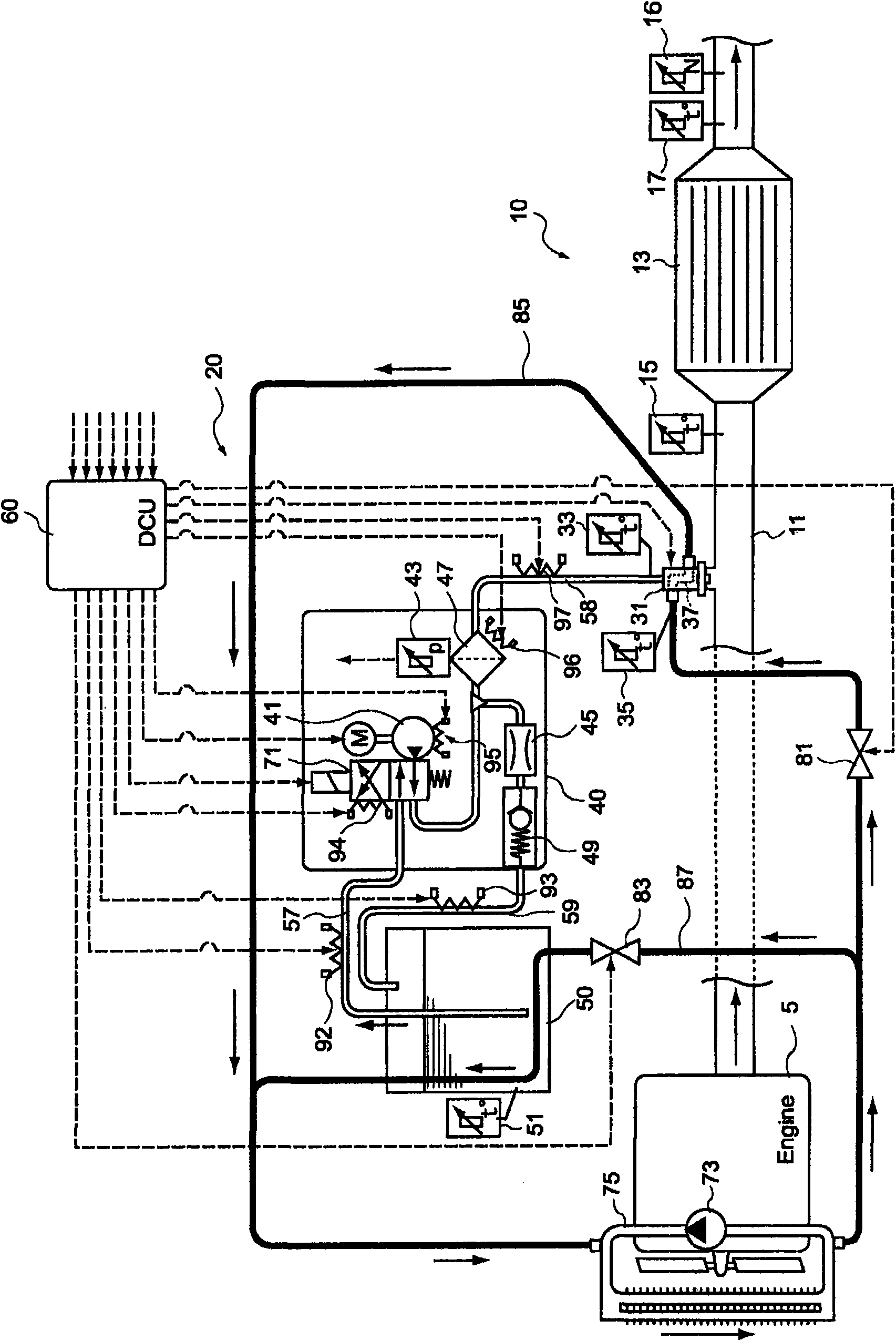
[0030] First, refer to figure 1 An example of the configuration of an exhaust purification device equipped with the reducing agent supply device of the present embodiment will be described.

[0031] figure 1The exhaust purification device 10 shown injects and supplies an aqueous urea solution as a liquid reducing agent to the upstream side of a reduction catalyst 13 arranged in the exhaust p...


PUM


Abstract

A reducing agent supply unit that prevents any heat damaging of reducing agent injection valve and also prevents any crystallization of urea solution by excessive cooling of liquid reducing agent; and a method of controlling the same. There is disclosed a reducing agent supply unit for use in an exhaust purification apparatus capable of feeding by injection a urea solution as a reducing agent on the along-exhaust upstream side of a reduction catalyst disposed along an exhaust path of internal combustion engine so as to attain reduction purification of any nitrogen oxides contained in exhaust gas by the reduction catalyst, which reducing agent supply unit has a reducing agent injection valve fixed to an exhaust pipe on the along-exhaust upstream side of the reduction catalyst. The reducing agent supply unit comprises a cooling water circulation path for circulating at least a portion of the cooling water of the internal combustion engine in order to cool the reducing agent injection valve; flow rate control means for regulating the flow rate of cooling water through the cooling water circulation path; temperature detection means for detecting the temperature of the reducing agent injection valve; and control means for controlling the flow rate control means on the basis of the temperature of the reducing agent injection valve.

Description

technical field [0001] The present invention relates to a reducing agent supply device and a control method used in an exhaust gas purification device. In particular, it relates to a reducing agent supply device and a control method of the reducing agent supply device configured to cool a reducing agent injection valve by using a urea solution as a reducing agent and circulating cooling water for cooling an internal combustion engine. Background technique [0002] Conventionally, in the exhaust gas discharged from internal combustion engines such as diesel engines, nitrogen oxides (hereinafter referred to as NO X ). as in order to put the NO X The exhaust purification device used for purification is known to spray and supply a liquid reducing agent such as urea solution into the exhaust gas on the upstream side of the reduction catalyst arranged in the exhaust passage, and to inject NO into the reduction catalyst. X Selective reduction purification exhaust gas purificatio...

Claims


Application Information

Patent Timeline
Patent Type & Authority Applications(China)
IPC IPC(8): F01N3/08F01P3/12F01P3/16B01D53/34B01D53/56B01D53/74B01D53/94
CPCB01D53/9431F01N2900/1811F01N2610/10F01N2900/1812F01N2610/11B01D2251/2067F01N2610/1473F01N2610/1433Y02T10/24F01P3/20F01N2260/024F01N3/208F01P2060/16F01N2610/02Y02T10/12
Inventor 土门涉五十岚洋之中尾英志
Owner BOSCH CORP
Why Eureka
Try Eureka