Lime calcining method and star-shaped kiln device

A kiln and lime technology, which is applied to the field of lime kiln burning in star-shaped kilns, can solve the problems of increased equipment investment and operating costs, difficult operation, low combustion efficiency, etc. Effect

Active Publication Date: 2012-04-18
SHIJIAZHUANG XINHUA IND FURNACE CO LTD
View PDF1 Cites 0 Cited by
  • Summary
  • Abstract
  • Description
  • Claims
  • Application Information

AI Technical Summary

Problems solved by technology

However, this process still has its disadvantages: ①It needs a special combustion chamber, which is not easy to operate; ②The heat of the hot air after cooling the lime is used through the heat exchanger, and the combustion efficiency is low, which increases the equipment investment and operating costs.

Method used


Image

  • Lime calcining method and star-shaped kiln device
  • Lime calcining method and star-shaped kiln device
  • Lime calcining method and star-shaped kiln device

Examples


Embodiment 1

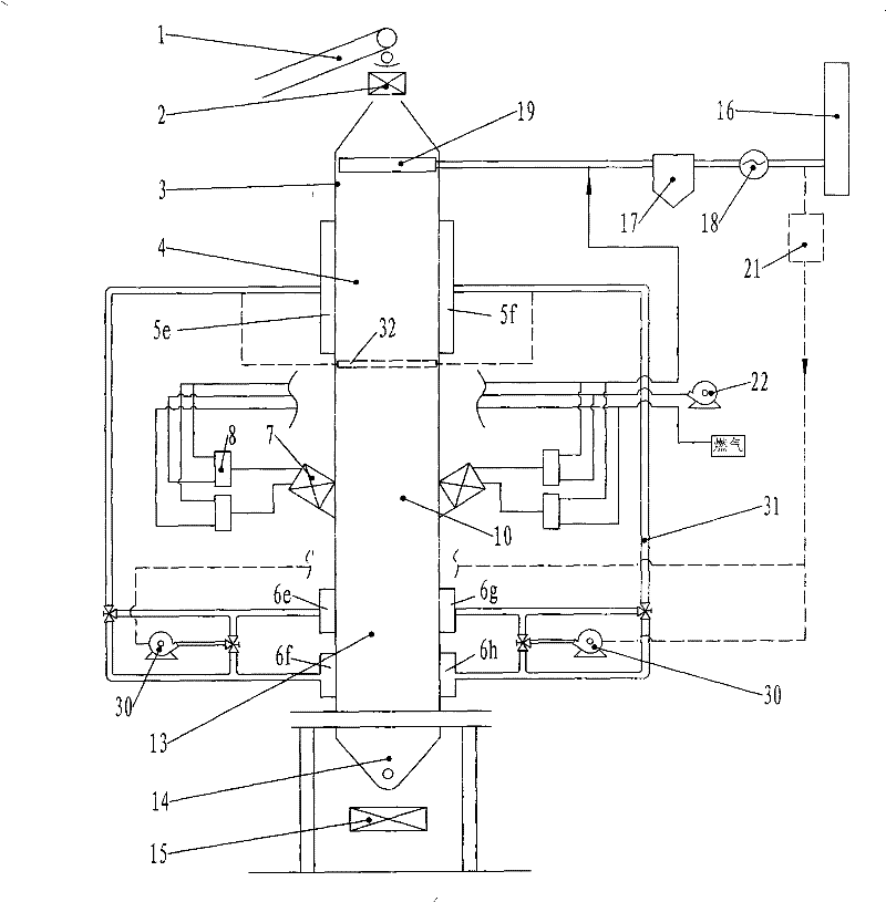
[0032] The star kiln device of the present invention is as figure 1 As shown, it includes a kiln body 3, a raw material conveyor 1, a feeding device 2, a discharging device 15, a heat storage pipeline 31, a fuel system, an air supply system and an exhaust gas discharge system. The kiln body is a vertical kiln structure, and the cross section of the kiln body is rectangular. The kiln body is divided into a preheating zone 4 , a calcining zone 10 and a cooling zone 13 . The upper part of the preheating zone is provided with 3 waste gas suction beams 19, which are used to suck the waste gas after preheating the materials. The suction holes on the suction beams are arranged reasonably according to other conditions such as furnace conditions and furnace size. The kiln walls on both sides of the calcination zone are equipped with burners. The burners are high-temperature regenerative burners 7. The high-temperature regenerative burners are equipped with regenerators. The regenerator...

Embodiment 2

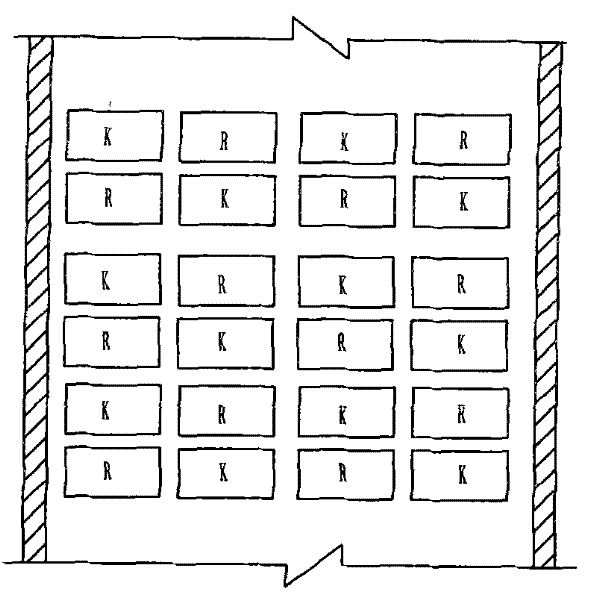
[0039] The star kiln device of the present invention is as Figure 9 As shown, it includes a kiln body 3, a raw material conveyor 1, a feeding device 2, a discharging device 15, a fuel system, an air supply system and an exhaust gas discharge system. The kiln body is a vertical kiln structure, the cross section of the kiln body is rectangular, and the kiln body is divided into a preheating zone 4, a calcining zone and a cooling zone 13. The upper part of the preheating zone is provided with two waste gas suction beams 19, which are used to suck the waste gas after preheating the materials. The exhaust gas suction beam is drawn away from the kiln body and connected with the dust collector 17, the induced draft fan 18 and the chimney 16. Burners 7 are installed on the opposite sides of the kiln walls of the calcining zone 10. The burners are high-temperature regenerative burners, and heat storage bodies are housed in the high-temperature regenerative burners.

[0040] In order...


PUM


Abstract

The invention provides a lime calcining method and a star-shaped kiln device. In a calcining zone, fuel gas and combustion-supporting air enter a kiln body from a nozzle on one side of the kiln to burn and leave the kiln body from the other side after limestone is calcined; the nozzles on both sides run alternatively; in a preheating zone, hot air enters the kiln body from both sides and is sucked out from a pumping beam on the upper part after the limestone is preheated; in a cooling zone, cooling air enters the kiln body from one side, transversely flows through a lime layer and exits from the other side after the limestone is cooled; and after the lime is cooled in the cooling zone, hot air flows to the preheating zone to preheat a limestone material. The calcining zone of the device is provided with a high-temperature regenerative burner; and opposite kiln walls on both sides of the preheating band and the cooling band are provided with air holes corresponding to a gas collecting device in a respective region. The method and the device have the advantages of energy conservation and high processed lime quality. Simultaneously, the method and the device can be suitable for processing limestone materials with small particle sizes.

Description

technical field [0001] The invention relates to a method and a device for calcining materials, in particular to a method and a device for burning lime in a star kiln. Background technique [0002] Lime and light dolomite are important building materials, as well as important raw materials in the fields of metallurgy and chemical industry. The prior art uses dolomite and limestone as raw materials, and adopts a vertical kiln with burning beams to calcinate lime. Such a process has the following defects. The direction of furnace gas flow in the shaft kiln is opposite to that of the stone material, that is, the stone material moves from top to bottom, and the furnace gas flows from bottom to top. Gas segregation occurs, causing uneven heating of limestone and affecting product quality. The applicant disclosed a utility model patent with the patent number ZL200320111077.3 for an internally and externally heated lime furnace. The combustion system of the lime furnace is provided...

Claims


Application Information

Patent Timeline
Patent Type & Authority Patents(China)
IPC IPC(8): C04B2/12
CPCY02P40/40
Inventor 贾会平
Owner SHIJIAZHUANG XINHUA IND FURNACE CO LTD
Why Eureka
Try Eureka