Annular slit restrictor

A technology for annular gaps and restrictors, which is applied to bearings, bearing components, shafts and bearings, etc., can solve the problems of restrictors with complex structures, large space requirements, and easy blockage, and achieve compact structure, simple adjustment, and not easy to block Effect

Inactive Publication Date: 2010-09-15
XI AN JIAOTONG UNIV +1
View PDF0 Cites 16 Cited by
  • Summary
  • Abstract
  • Description
  • Claims
  • Application Information

AI Technical Summary

Problems solved by technology

[0004] The purpose of the present invention is to provide a device that can solve the problems of complex structure, easy blockage, and large space requirements of the existing static pressure support system throttle, so that the fixed throttle can meet the requirements of excellent performance, compact structure, convenient disassembly and assembly, and not easy to block. annular gap restrictor

Method used


Image

  • Annular slit restrictor
  • Annular slit restrictor
  • Annular slit restrictor

Examples


Embodiment Construction

[0014] The structure and working principle of the present invention will be further described in detail below in conjunction with the accompanying drawings.

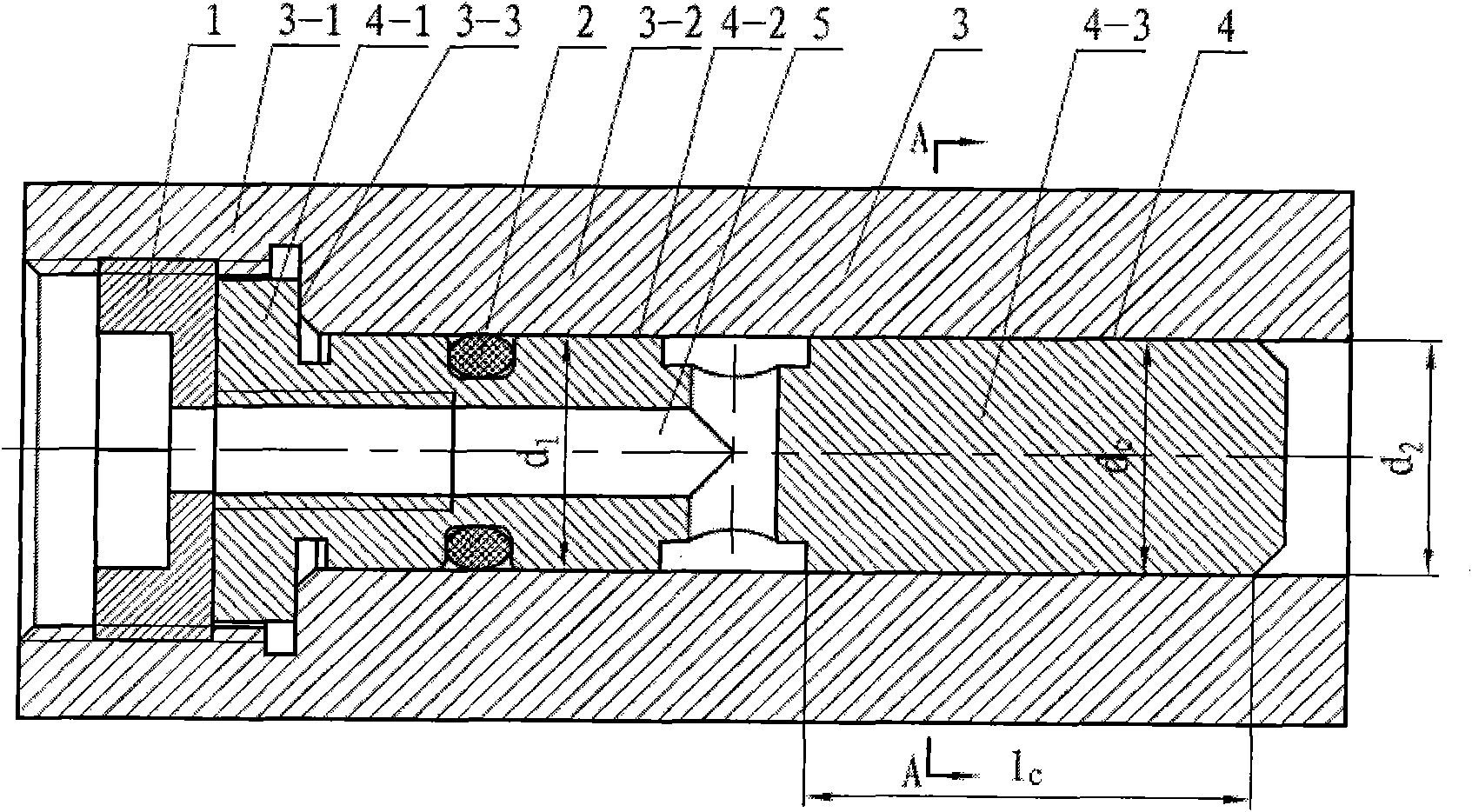
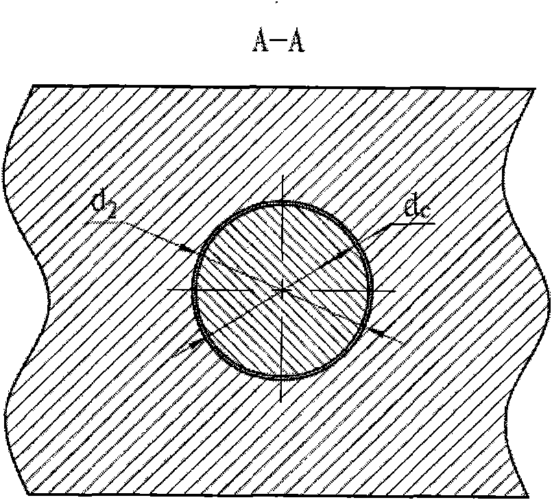
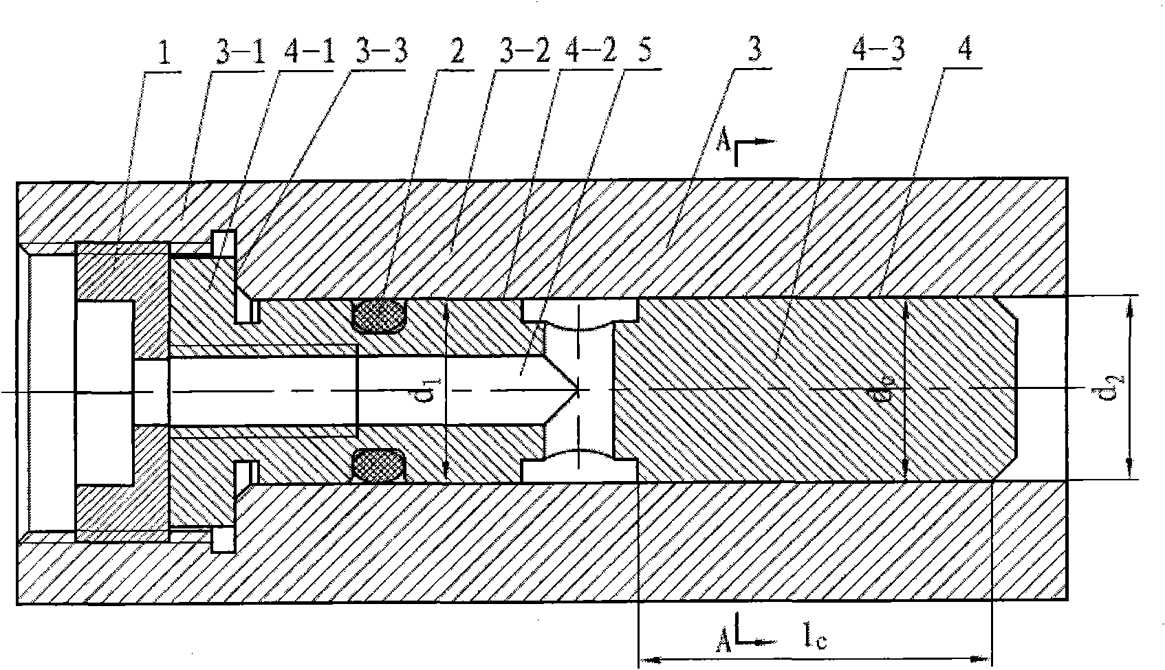
[0015] see figure 1 , the present invention includes a throttle installation body 3 and a throttle body 4 arranged in the throttle installation body 3, the throttle installation body 3 is composed of a stepped front cavity 3-1, a rear cavity 3- 2 and the hole shoulder 3-3, the diameter of the front cavity 3-1 is greater than the diameter d of the rear cavity 3-2 2 , the throttle body 4 is composed of a stepped front end 4-1, a middle part 4-2 and a rear end 4-3, the diameter of the front end 4-1 is greater than the diameter d of the middle part 4-2 1 and the diameter d of the rear end 4-3 c , the diameter d of the middle part 4-2 1 greater than the diameter d of the rear end 4-3 c , the front end 4-1 of the restrictor body 4 is axially positioned by the hole shoulder 3-3 of the restrictor mounting body 3, and fixed b...


PUM


Abstract

The invention relates to annular slit restrictor comprising a restrictor mounting body and a restrictor body. The restrictor body is arranged in the restrictor mounting body; the restrictor mounting body comprises a step-shaped front end cavity and a step-shaped rear end cavity; the restrictor body comprises a step-shaped front end part, a step-shaped middle part and a step-shaped rear part, wherein the front end part is axially positioned by hole shoulder of the restrictor mounting body, and the middle part and the rear part are arranged in the rear end cavity of the restrictor mounting body; the middle part of the restrictor body is axially matched with the rear end cavity of the restrictor mounting body; the diameter of the rear part of the restrictor body is smaller that that of the rear end cavity of the restrictor mounting body; the slit between the rear part of the restrictor body and the rear end cavity of the restrictor mounting body forms the working zone of the annular slit restrictor; and the front end part and the middle part of the restrictor body are provided with through holes which are communicated with the working zone. The annular slit restrictor meets the requirement of compact structure, convenient assembly and disassembly, easy adjustment, stable performance and less susceptibility to block.

Description

technical field [0001] The invention relates to a restrictor for hydrostatic support, in particular to an annular gap restrictor for hydrostatic support in ultra-precision machine tools. Background technique [0002] Hydrostatic bearings have the advantages of small frictional resistance, long service life, wide speed range, good anti-vibration performance, high precision, and good adaptability, so they are widely used in ultra-precision machine tools. [0003] The restrictor is a necessary and very important component in the constant pressure oil supply hydrostatic support system, which plays the role of automatically adjusting the pressure of the oil chamber, so that the constant pressure oil supply hydrostatic support system has the corresponding oil film bearing capacity and oil film stiffness . Commonly used restrictors mainly include fixed restrictors and variable restrictors. Although the variable restrictor can make the static stiffness of the support reach infinit...

Claims


Application Information

Patent Timeline
Patent Type & Authority Applications(China)
IPC IPC(8): F16C41/00F16C32/06
Inventor 赵万华陈耀龙何仲赟王智伟薛飞卢秉恒
Owner XI AN JIAOTONG UNIV
Why Eureka
Try Eureka