Solar silicon cell nanosecond-pulse green laser scriber

A technology of nanosecond pulses and silicon batteries, applied in laser welding equipment, circuits, electrical components, etc., can solve the problems of large spot, wide scratches, and large deviation of resonance absorption frequency, etc., and achieve uniform distribution of spot intensity, The effect of reducing the spot diameter and increasing the power density

Inactive Publication Date: 2010-09-22
ANHUI INST OF OPTICS & FINE MECHANICS - CHINESE ACAD OF SCI +1
View PDF0 Cites 7 Cited by
  • Summary
  • Abstract
  • Description
  • Claims
  • Application Information

AI Technical Summary

Problems solved by technology

However, this laser scribing machine has shortcomings. First of all, the anti-cavity sheet and the output cavity sheet in the Nd:YAG laser component are both flat mirrors. This unstable critical cavity not only makes the laser output power stable. The performance is extremely poor, and the output laser mode and spot intensity distribution are not uniform
That is, the output laser beam has a Gaussian distribution, the center of which is the strongest, and the two sides are distributed with a Gaussian function drop. After this non-flat-top laser beam is focused on the silicon wafer, the scribing line formed by the scribing result is V-shaped. The laser intensity at the edge is weak and does not meet the conditions for silicon vaporization. It only melts or ablates the silicon material, and does not play a cutting role at all, so that it is difficult to guarantee the quality of scribing. There is a certain damage rate, which makes the production cost difficult. Secondly, the wavelength of the laser beam emitted by the Nd:YAG laser component is 1064nm, which has a large deviation from the resonant absorption frequency of the silicon wafer, and has the defect of a large spot after focusing under the same divergence angle; again, the laser The Q switcher on the oscillating circuit is an acousto-optic Q switcher. The pulse width of the laser output after Q switch is relatively wide, about 150ns, which causes the energy density of the laser per unit time is not high enough, making the scribing depth Not ideal, the scratches are wide, and the ablation of the silicon wafer is serious, and the smoothness is poor

Method used


Image

  • Solar silicon cell nanosecond-pulse green laser scriber
  • Solar silicon cell nanosecond-pulse green laser scriber

Examples


Embodiment Construction

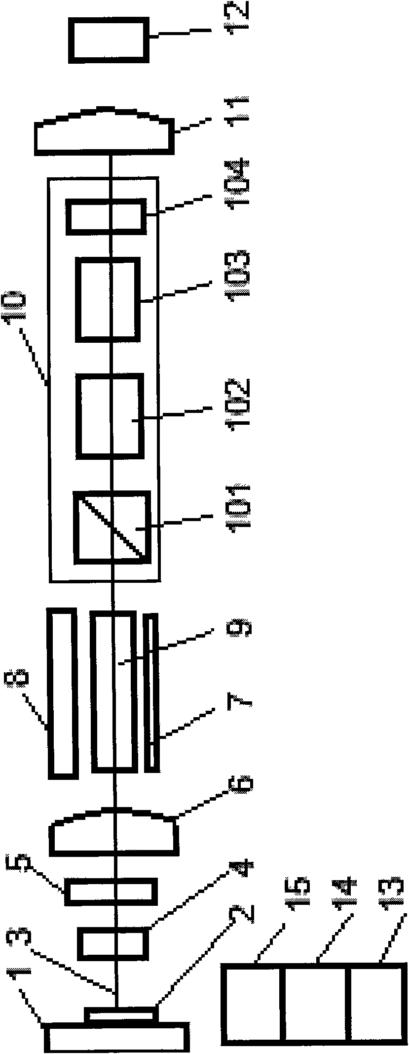
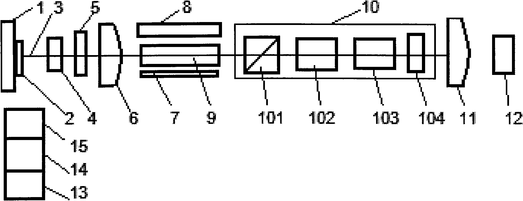
[0013] see figure 1 The nanosecond pulsed green laser scribing device for solar silicon cells includes laser components and a two-dimensional electric shift stage 1 on its output optical path 3 , water cooling components 13 , laser power supply 14 and machine control components 15 . in,

[0014] The laser component includes a total anti-cavity plate, a Q switcher, a laser rod 9 and an output cavity plate arranged in sequence on the laser oscillating circuit. Wherein: the output cavity sheet is a Gaussian mirror 6, and the total anti-cavity sheet is a concave mirror 11 complementary to the Gaussian mirror 6; the Q switcher is an electro-optical Q switcher 10, which is connected in series on the laser oscillation circuit A polarizer 101, a first Q-switching crystal 102, a second Q-switching crystal 103 and a 1 / 4 wave plate 104, the first Q-switching crystal 102 and the second Q-switching crystal 103 are gallium lanthanum silicate crystals, here Gallium lanthanum silicate cryst...


PUM


Abstract

The invention discloses a solar silicon cell nanosecond-pulse green laser scriber. The solar silicon cell nanosecond-pulse green laser scriber comprises a laser component, a two-dimensional electro-migration platform (1), a water cooling component (13), a laser power supply (14) and a complete machine control component (15), wherein the two-dimensional electro-migration plateform (1) is arranged on the light path (3) of the laser component; the laser component comprises an all-trans cavity plate, a Q-regulator, a laser bar (9) and an output cavity plate; particularly, the output cavity plate is a Gauss mirror (6), and the all-trans cavity plate is a concave mirror (11) which is complementary with the Gauss mirror (6); the light path (3) between the Gauss mirror (6) and the two-dimensional electro-migration platform (1) is provided with a double-frequency crystal (5) the non-transmission surface of which is provided with a semiconductor cooler; and the Q-regulator is an electro-optical Q-regulator (10) consisting of a polarizer (101), a first Q-regulation crystal (102), a second Q-regulation crystal (103) and a 1 / 4 wave plate (104) which are connected in series. The width of the scribed seam is 50 mu m, and the precision is 10 mu m. The invention increases the scribing speed and depth by 50%, enhances the scribing efficiency and lowers the production cost.

Description

technical field [0001] The invention relates to a laser scribing device, in particular to a solar silicon cell nanosecond pulse green laser scribing device. Background technique [0002] The dicing machine is the key and necessary equipment in the production of solar silicon cells - solar panel components. At present, there are two types of scribing machines commonly used: mechanical scribing machine and laser scribing machine. The laser scribing machine is mainly composed of Nd:YAG laser components and a two-dimensional electric shift stage on its output optical path, as well as water cooling components, laser power supply and machine control components. Among them, the Nd:YAG laser components are composed of It is composed of a total anti-cavity chip, a Q-switcher, a laser rod and an output cavity chip in sequence, and the control components of the whole machine are electrically connected with the two-dimensional electric shift stage, the laser power supply and the Q-swit...

Claims


Application Information

Patent Timeline
IPC IPC(8): B23K26/00H01L21/78H01L31/18B23K26/38
CPCY02P70/50
Inventor 江海河袁自钧吴先友
Owner ANHUI INST OF OPTICS & FINE MECHANICS - CHINESE ACAD OF SCI
Why Eureka
Try Eureka