X-ray radiographic digital imaging detection method for power grid GIS (Geographic Information System) equipment

A detection method and digital imaging technology, applied in the direction of using radiation for material analysis, etc., to achieve the effect of reducing the number of photos and improving work efficiency

Inactive Publication Date: 2010-09-22
ELECTRIC POWER RESEARCH INSTITUTE OF STATE GRID QINGHAI ELECTRIC POWER COMPANY
View PDF5 Cites 29 Cited by
  • Summary
  • Abstract
  • Description
  • Claims
  • Application Information

AI Technical Summary

Problems solved by technology

[0004] As a non-destructive testing technology that can penetrate objects and image the internal structure of objects, X-ray has been widely used in medicine, aviation, petrochemical, railway and other industries. It is a non-destructive testing technology for rapid imaging. Applying this technology The imaging of the internal structure of the power grid GIS (gas insulated metal-enclosed switch) equipment has not yet been recorded

Method used


Image

  • X-ray radiographic digital imaging detection method for power grid GIS (Geographic Information System) equipment
  • X-ray radiographic digital imaging detection method for power grid GIS (Geographic Information System) equipment
  • X-ray radiographic digital imaging detection method for power grid GIS (Geographic Information System) equipment

Examples


Embodiment 1

[0040] 1) Determine that the part to be photographed is the isolation switch of the power grid GIS equipment;

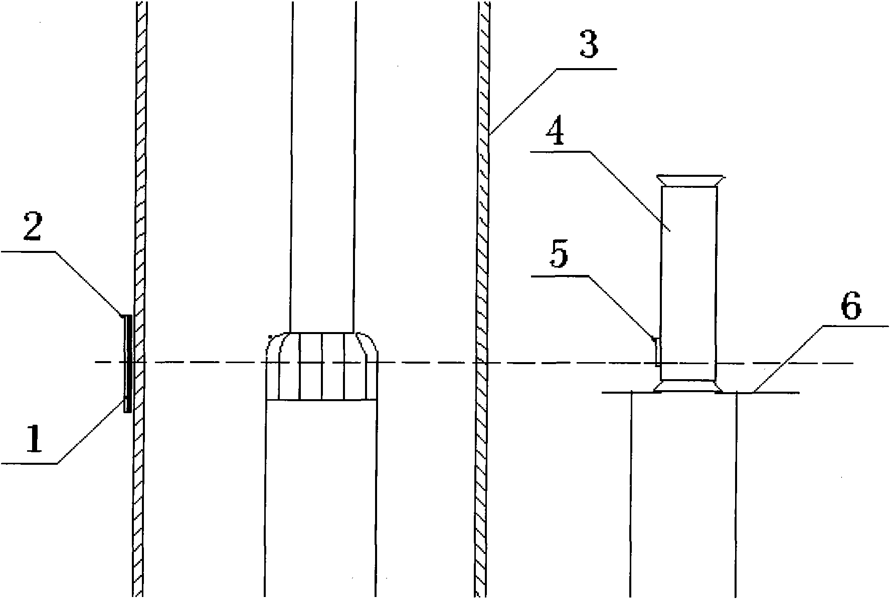
[0041] 2) Erecting of the X-ray machine 4 and placement of the X-ray photosensitive imaging plate 1 Place the X-ray machine 4 fixed on the X-ray machine bracket 6 firmly on the shooting platform so that the ray emission window 5 is vertically aligned with the area to be photographed. Part 3 is the isolation knife gate. The X-ray photosensitive imaging plate 1 is placed close to the equipment shell in the direction opposite to the radiation emission window 5 on the back of the isolation knife gate of the object to be photographed. The center of the radiation-sensitive imaging plate 1 is on a straight line;

[0042] 3) Connect the cables between the X-ray machine 1 and the console, and check that the console and the X-ray machine 4 are operating normally;

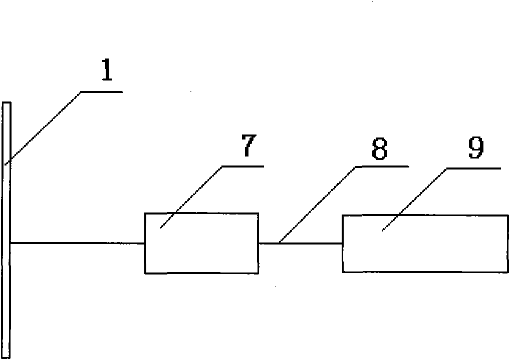
[0043] 4) Connect the CR digital image scanner 7 and the computer 9 through the dedicated data 8-wire, and check...

Embodiment 2

[0050] 1) Determine that the part to be photographed is a circuit breaker;

[0051] 2) Erecting of the X-ray machine 4 and placement of the X-ray photosensitive imaging plate 1 Place the X-ray machine 4 fixed on the X-ray machine bracket 6 firmly on the shooting platform so that the ray emission window 5 is vertically aligned with the area to be photographed. Part 3 is the circuit breaker cylinder. The X-ray photosensitive imaging plate 1 is placed close to the equipment casing, namely the circuit breaker cylinder, on the back of the object to be photographed, that is, the back of the circuit breaker and the direction opposite to the radiation emission window 5. The center of the radiation emission window 5 is aligned with The equipment needs to shoot the part 3, and the center of the X-ray photosensitive imaging plate 1 is on a straight line;

[0052] 3) Connect the cables between the X-ray machine 1 and the console, and check that the console and the X-ray machine 4 are oper...

Embodiment 3

[0060] 1) Determine that the part to be photographed is the busbar barrel;

[0061] 2) Erecting of the X-ray machine 4 and placement of the X-ray photosensitive imaging plate 1 Place the X-ray machine 4 fixed on the X-ray machine bracket 6 firmly on the shooting platform so that the ray emission window 5 is vertically aligned with the area to be photographed. Part 3 is the busbar cylinder body. Place the X-ray photosensitive imaging plate 1 close to the equipment casing in the direction opposite to the ray emission window 5 on the back of the object to be photographed. The center of the ray emission window 5 is in contact with the equipment to be photographed The center of the imaging plate 1 is on a straight line;

[0062] 3) Connect the cables between the X-ray machine 1 and the console, and check that the console and the X-ray machine 4 are operating normally;

[0063] 4) Connect the CR digital image scanner 7 and the computer 9 through the dedicated data 8-wire, and check...


PUM


Abstract

The invention relates to a power grid equipment detecting technology, in particular to an X-ray radiographic digital imaging detection method for power grid GIS (Geographic Information System) equipment. The detection method comprises the following steps of: (1) fixing a part needing to be shot; (2) erecting an X-ray apparatus and placing an X-ray sensitization imaging plate; (3) connecting a cable between the X-ray apparatus and a console; (4) connecting a CR (Conditioned Reflex) digital image scanner and a computer by a special data line; (5) setting a shooting parameter of the X-ray apparatus according to the field condition; (6) starting a high-voltage emitting button of the console and carrying out radiographic shooting; (7) reading data to obtain a digital image picture; and (8) processing a shooting result by the computer. An X-ray radiographic digital imaging system of the GIS equipment directly reads data of an IP (Internet Protocol) imaging plate by adopting an advanced CR digital image scanning technology and converts the sensitizing image information on the IP imaging plate into a digital image signal; and compared with the traditional ray film needing a darkroom and the step of developing, the working efficiency is greatly improved.

Description

technical field [0001] The invention relates to a power grid equipment detection technology, in particular to a power grid GIS equipment X-ray transillumination digital imaging detection method. Background technique [0002] With the continuous development and expansion of the power grid, GIS equipment is more and more widely used in the power industry due to its stable operation, compact structure, and low external interference, and has become the development direction of electrical equipment in substations in the current power industry. Components include circuit breakers, isolating switches, grounding switches, voltage and current transformers, lightning arresters, bushings (cable terminals), busbars, etc. Among them, circuit breakers are responsible for cutting off and connecting large-load electric energy, and are the core components of GIS equipment , consisting of an arc extinguishing chamber and an operating mechanism; the isolating switch is used to break a small cu...

Claims


Application Information

Patent Timeline
Patent Type & Authority Applications(China)
IPC IPC(8): G01N23/04
Inventor 闫斌何喜梅李生平王志惠李军吴童生
Owner ELECTRIC POWER RESEARCH INSTITUTE OF STATE GRID QINGHAI ELECTRIC POWER COMPANY
Why Eureka
Try Eureka