Energy-saving and emission-reducing device for coke dry quenching and energy-saving and emission-reducing coking process using same

A technology for energy saving, emission reduction and coke dry quenching. It is applied in coke ovens, gasification processes, and coke cooling. It can solve the problems of low heat utilization efficiency and no effect on carbon dioxide emission reduction, and achieve good industrial prospects and low costs. , the effect of high efficiency

Inactive Publication Date: 2010-09-29
BEIJING SHUOREN HAITAI ENERGY ENVIRONMENT TECH
4 Cites 16 Cited by

AI-Extracted Technical Summary

Problems solved by technology

[0003] The technical problem to be solved by the present invention is to overcome the limitations and deficiencies of the above-mentioned prior art that have low heat utilization efficiency and have no effect on the reduction of carbon ...

Method used

In this example, the cooling section furnace wall is a water-cooled wall, and the water-cooled pipe 7 arranged and distributed is arranged in the wall, and the cooling water is passed inside, and the water-cooled wall is coated with wear-resistant material 29, which can avoid the excessive coke of falling and the water pipe of the cooling wall friction, causing the water pipe to rupture.
The CDQ energy-saving emission reduction device of the present invention preferably adopts the form of spiral discharge to discharge coke, more preferably adopts the frequency conversion speed regulation motor to drive the spiral discharger, adjusts discharge speed and frequency conversion speed regulation according to the coke discharge design value The speed of the motor is controlled by the speed and the design of the spiral to control the coke discharge speed. Considering the harmfulness of the cooled gas to the human body and the environment, a water seal is used at the coke discharge outlet to prevent gas leakage and air entry, and a water seal is used at the coke outlet to discharge the water seal water and coke together, which can minimize the coke in the end. The safe temperature can also prevent the gas from escaping, avoiding its harm to the environment and human body, and preventing air from entering the reduction cooler to ignite coke, thereby preventing explosions.
[0030] The internal water wall can be arranged in a criss-cross arrangement as shown in Figure 2, or in a horizontal arrangement (not shown in the figure). The intersecting or horizontal internal ...

Abstract

The invention provides an energy-saving and emission-reducing device for coke dry quenching and an energy-saving and emission-reducing coking process using same, which can realize energy saving and emission reduction with high efficiency and low cost. The invention has the advantages that the emission of carbon dioxides in flue gas is reduced in the coke quenching process, valuable carbon monoxide is generated, and low-cost feed gas is provided for downstream products to synthesize ammonia, methanol and the like while coke quenching, thereby being a new method for realizing energy saving and emission reduction in the coke production and having excellent industry prospects and wide social benefits.

Application Domain

Technology Topic

Image

  • Energy-saving and emission-reducing device for coke dry quenching and energy-saving and emission-reducing coking process using same
  • Energy-saving and emission-reducing device for coke dry quenching and energy-saving and emission-reducing coking process using same
  • Energy-saving and emission-reducing device for coke dry quenching and energy-saving and emission-reducing coking process using same

Examples

  • Experimental program(1)

Example Embodiment

[0026] The specific embodiments of the present invention will be described in detail below in conjunction with the accompanying drawings.
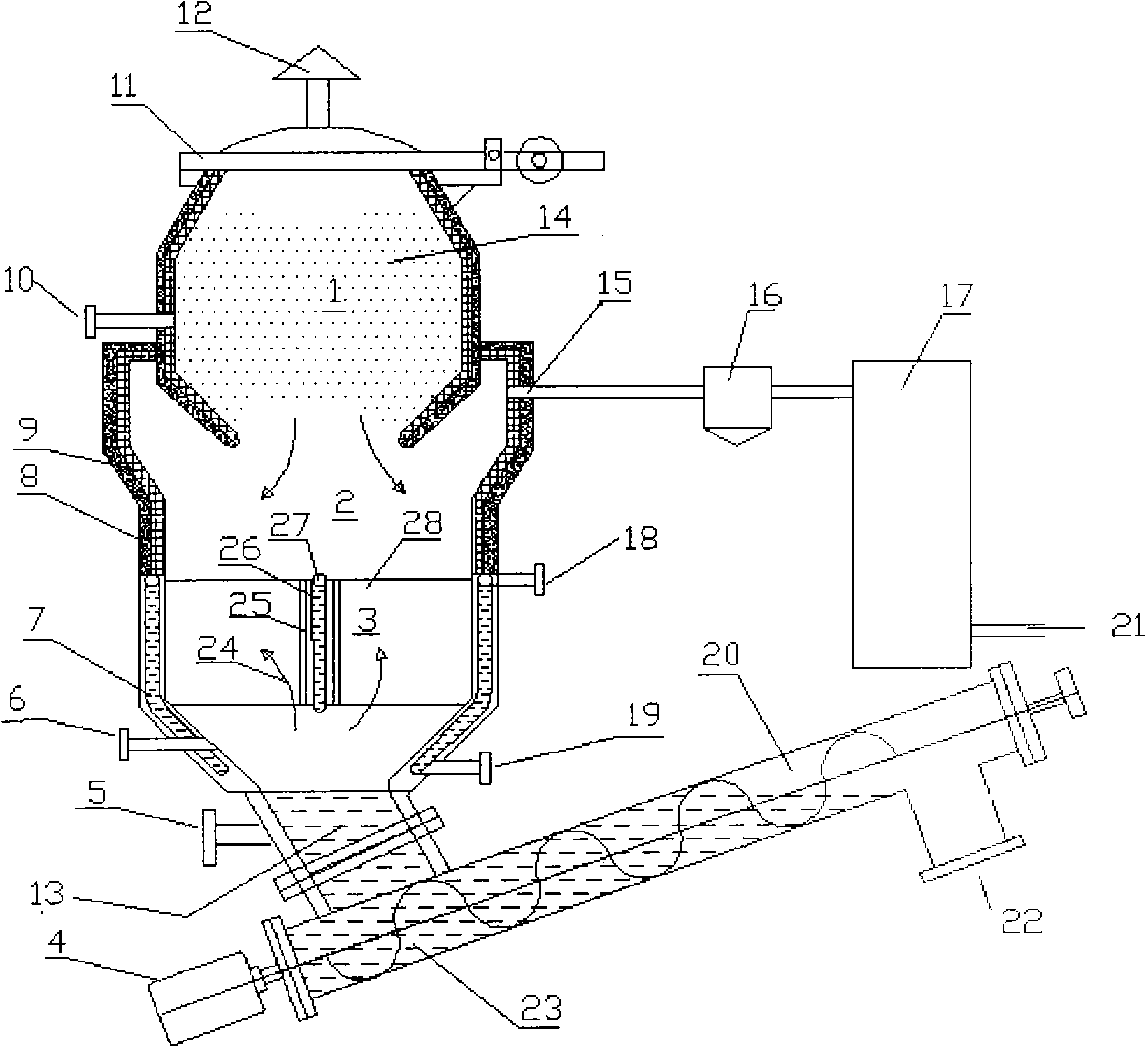
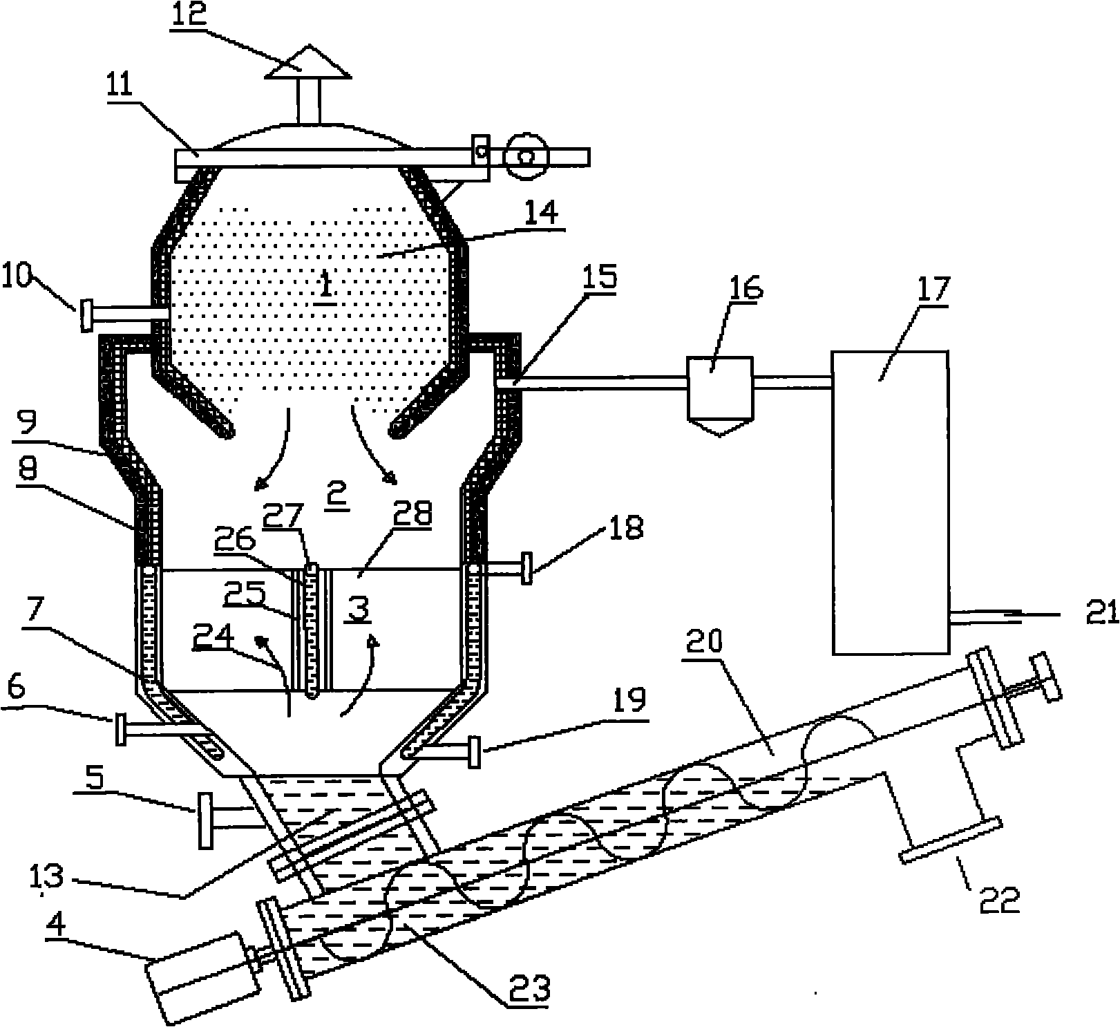
[0027] As attached figure 1 The CDQ energy-saving emission reduction device of the present invention shown includes a fan connected to the sequential air ducts, a reduction cooler, a dust collector 16 and a waste heat boiler 17, and a fan (not shown in the figure) is placed in front of the reduction cooler. The reduction cooler is divided from top to bottom into a combustion chamber 1, a reduction section 2 and a cooling section 3. Among them, the top of the combustion chamber 1 is provided with a furnace cover 11, and an air inlet 10 is opened on the furnace wall in the lower part of the combustion chamber; There is a gas outlet 15 on the upper furnace wall, which communicates with the dust collector through a gas outlet pipe and further communicates with the waste heat boiler 17; a CO2 inlet 6 is opened on the lower furnace wall of the cooling section; the cooling section 3 gradually shrinks downwards A coke discharge outlet 13 is formed, and the coke discharge outlet 13 is in communication with the water-sealed screw discharger 20.
[0028] In this example, the furnace wall of the cooling section is a water-cooled wall, and water-cooled pipes 7 arranged and distributed in the wall are provided with cooling water. The water-cooled wall is coated with a wear-resistant material 29 to avoid excessive friction between the falling coke and the water pipe of the cooling wall. water pipe breakage.
[0029] The cooling section of the present invention can also be provided with internal water walls according to the production capacity and the size of the reduction cooler, and the water pipes in the internal water walls are communicated with the water pipes of the furnace body to jointly participate in coke cooling and generate steam. Because the thermal conductivity of coke is small, that is, the thermal resistance is large. When the cross-sectional area of ​​the cooling section is large, the heat of the central coke cannot be transmitted in time, and the cooling effect is poor. Therefore, the internal water wall can be installed to remove the The coke heat is taken away in time.
[0030] The internal water wall can be like figure 2 The cross arrangement shown may also be a horizontal arrangement (not shown in the figure). The crossed or horizontally arranged internal water walls can also play the role of evenly distributing gas: the gas sent from the bottom of the reduction device can be evenly distributed to the spaces separated by the internal water walls through the gas distributor.
[0031] The internal water wall is provided with fins at a certain interval, the width of the fin is 50mm-100mm, the interval between adjacent fins is 50mm-80mm, and the length of the fin is the height of the cooling section. The fins can increase the heat dissipation area of ​​the coke to the water wall, that is, increase the heat transfer area of ​​the water wall and the coke. Please tell me that the internal water wall can further reduce the temperature of the coke, is there anything else? The width of the fins can be the same, and preferably the widths of adjacent fins are different. The difference in width can avoid the blockage of coke erected in the middle of the fins and affect production.
[0032] The furnace walls of the combustion chamber and the reduction section of the present invention have a double-layer structure, the inner wall is made of ordinary refractory bricks, and the outer periphery is covered with insulation materials.
[0033] The CDQ energy-saving emission reduction device of the present invention preferably adopts the form of spiral discharging for coke discharge, and more preferably uses a frequency conversion speed regulating motor to drive the screw discharger, and adjusts the discharge speed and the rotation speed of the frequency conversion speed regulating motor according to the design value of coke displacement , Control the defocusing speed through the design of the rotation speed and the spiral. Taking into account the harmfulness of the gas to the human body and the environment after cooling, the coke discharge outlet uses a water seal to prevent gas leakage and air entry, and the coke discharge adopts a water seal, so that the water and coke are discharged together, which can reduce the coke to the maximum. The safe temperature can also prevent the escape of gas, avoid its harm to the environment and human body, and prevent air from entering the reduction cooler to ignite the coke, thereby preventing an explosion.
[0034] The coking energy saving and emission reduction process of the present invention using the aforementioned CDQ energy saving and emission reduction device is realized as follows: the fan is placed in front of the reduction cooler, and the red hot coke is loaded from the top of the reduction cooler by the loading device, and the reduction cooling The gas outlet of the dust collector is connected with the inlet of the dust collector, and the outlet of the dust collector is connected with the waste heat boiler to form a continuous air duct. The carbon dioxide gas is blown into the reduction cooler from the bottom of the cooling section of the reduction cooler by a fan, and exchanges heat with the coke countercurrently. The temperature rises, and the heat absorption chemical reaction occurs in the reduction section of the reduction cooler. The boiler recovers heat, and the recovered carbon monoxide can be used as the raw material gas to enter the next chemical product synthesis process for ammonia, methanol and other production processes. In this way, part of the heat of the coke in the reduction section is consumed by the endothermic reaction of carbon dioxide and coke. The remaining heat is taken away by the cooling water of the coke in the water wall of the cooling section, and the cooling water generates steam, which can be used for power generation or other purposes. The coke that has reached the coke discharge temperature is discharged from the reduction cooler through the screw discharger, thereby greatly improving the heat utilization efficiency.
[0035] The specific implementation example of the coking energy saving and emission reduction process is as follows:
[0036] (1) Coke burning
[0037] Open the furnace cover, load the red hot coke from the top of the combustion chamber into the reduction cooler, determine the amount of air introduced through the temperature measurement, and introduce it into the combustion chamber through the air inlet; the coke burns, and finally the coke temperature rises to no more than 1200℃; C The higher the reaction temperature with CO2, the faster the reaction speed, but if it exceeds 1200°C, the coke will slag and stick to the wall, affecting the operation of the equipment. As the bottom coke discharge progresses, red hot coke that does not exceed 1200°C falls from the combustion chamber into the reduction section.
[0038] (2) Restore
[0039] In the process of this example, the temperature at which carbon dioxide enters the reduction cooler is 30°C, and the temperature gradually rises in the cooling section, rising to 750°C (with a difference of 50°C from the main body temperature of the coke) and enters the reduction section to react with the heat of reaction being 1731kcal /m 3 CO 2.
[0040] The coke processing capacity in the reduction cooler is 1t/h, and the coke temperature drops from 1050°C to 800°C. Here 800°C is the "termination" temperature of the reaction between coke and carbon dioxide, that is, the reaction basically does not occur below 800°C. The heat emitted is: 1000*0.3*(1050-800)=75000kcal/h
[0041] Where 0.3——the specific heat of coke, kcal/kg.℃
[0042] The amount of carbon dioxide required for the reaction: 75000/1731=43.4m 3
[0043] Where 1731——The reaction heat of carbon dioxide and carbon, kcal/m 3 CO 2
[0044] It can be seen that it takes 43.4m to process 1 ton of coke in the reduction section 3 Carbon dioxide, and produce 43.4*2=86.8m 3 The temperature of CO and CO is 850~950℃, which can produce medium and low pressure steam: 0.31*86.8*(900-200)/600000=0.03t;
[0045] In the formula, 0.31---CO 900℃ hot melt, unit cal/m 3.k;
[0046] 200---The temperature drops to 200℃ after the gas produces steam;
[0047] 600000---The heat required to produce 1t of medium and low pressure steam in the boiler, in cal/t.
[0048] When the carbon dioxide of the present invention reaches the reduction section, the temperature can rise to 750°C, 43.4m 3 The heat of coke taken away by heat exchange before carbon dioxide reaches the reduction section is:
[0049] 43.4*0.5*(750-30)=15624kcal/h
[0050] Where 0.5-specific heat of carbon dioxide, kcal/m 3.℃
[0051] However, 1 ton of coke emits 15624kcal heat and the temperature can be reduced by 15624/(1000*0.3)=52℃, that is, the coke temperature drops to 800-52=748℃.
[0052] The generated carbon monoxide is used as a raw material for the synthesis of chemical products, such as the synthesis of ammonia and methanol products; the chemical reaction of carbon dioxide and coke can take away 30%-40% of the sensible heat of the coke, and the heat of the generated high-temperature carbon monoxide is transferred from the waste heat boiler in the form of steam Recovery; stop the reaction at about 800°C.

PUM

no PUM

Description & Claims & Application Information

We can also present the details of the Description, Claims and Application information to help users get a comprehensive understanding of the technical details of the patent, such as background art, summary of invention, brief description of drawings, description of embodiments, and other original content. On the other hand, users can also determine the specific scope of protection of the technology through the list of claims; as well as understand the changes in the life cycle of the technology with the presentation of the patent timeline. Login to view more.

Similar technology patents

Classification and recommendation of technical efficacy words

  • Reasonable structure
  • Low cost

A ceramic insulator device for high voltage capacitor

InactiveCN101546636ALow manufacturing costReasonable structureSuspension/strain insulatorsHigh voltage capacitorsEngineering
Owner:王海龙

Semiconductor device

InactiveUS6975142B2Low costReduce manufacturing stepsTransistorSolid-state devicesVoltage amplitudeSemiconductor
Owner:SEMICON ENERGY LAB CO LTD
Why Eureka
Try Eureka