
Conductor electric exploding plasma-based low-energy metal ion implantation (PBLEMII) device

A metal ion implantation, plasma source technology, applied in ion implantation plating, metal material coating process, coating and other directions, can solve the problems of inability to handle metal pipe fittings, low bonding strength, protection failure, etc., to solve the bonding strength. The effect of limited, compact equipment and low manufacturing cost

Active Publication Date: 2012-06-13
DALIAN UNIV OF TECH
View PDF1 Cites 3 Cited by
  • Summary
  • Abstract
  • Description
  • Claims
  • Application Information

AI Technical Summary

Problems solved by technology

However, the application of this PBLEII technology to the ion implantation of the inner wall surface of metal pipes still has the following problems: the plasma generated by the external plasma source is introduced into the pipe, the plasma is unevenly distributed along the axial direction, and the ion sheath with a wide range of changes It affects the uniformity of surface injection, and it is not yet possible to treat the inner wall surface of metal pipes with small diameters or relatively large lengths and diameters; secondly, this technology is limited to gas plasma sources, and can only inject non-metal ions, not metal ions
In 1998, the article "Generation of a high velocity j et in the electrothermal explosion of conductive ceramic powders" published in the Journal of Thermal Spray Technology by H.Tamura et al first reported the test and analysis results of one-dimensional directional spraying using line explosion; In 2002, the invention patent US6467425B1 of H.Neff et al. introduced the method of utilizing conductor electric explosion to spray and prepare chrome coating on the inner wall of the gun barrel, which can solve the problem of low bonding strength between traditional electroplating chrome coating and workpiece, external force (impact force generated by ammunition explosion) ) under the action of the coating is prone to damage and peeling, which leads to the problem of protection failure
However, no matter whether the fine powder is prepared by the conductor electric explosion method or the inner surface of the metal pipe is sprayed, the free explosion product of the metal wire contains a large number of molten droplets and solid particles, and the electric explosion of the conductor wire has not been effectively used. Advantages as a metal plasma source
The reason is that the electric explosion process of the conductor bare wire or the slow rising edge pulse, the corona discharge on the surface of the conductor wire, and the local preferential melting of the conductor wire all lead to low energy deposition efficiency of the electric explosion, and most of the conductor wires are lower than the evaporation temperature. Fusion or explosion occurs, and the plasmaization efficiency of the conductor wire is low
Therefore, the electric explosion devices currently used for spraying and fine powder preparation are still not effective metal plasma sources

Method used


Image

  • Conductor electric exploding plasma-based low-energy metal ion implantation (PBLEMII) device
  • Conductor electric exploding plasma-based low-energy metal ion implantation (PBLEMII) device
  • Conductor electric exploding plasma-based low-energy metal ion implantation (PBLEMII) device

Examples


Embodiment Construction

[0022] The specific implementation manner of the present invention will be described below with reference to the accompanying drawings.

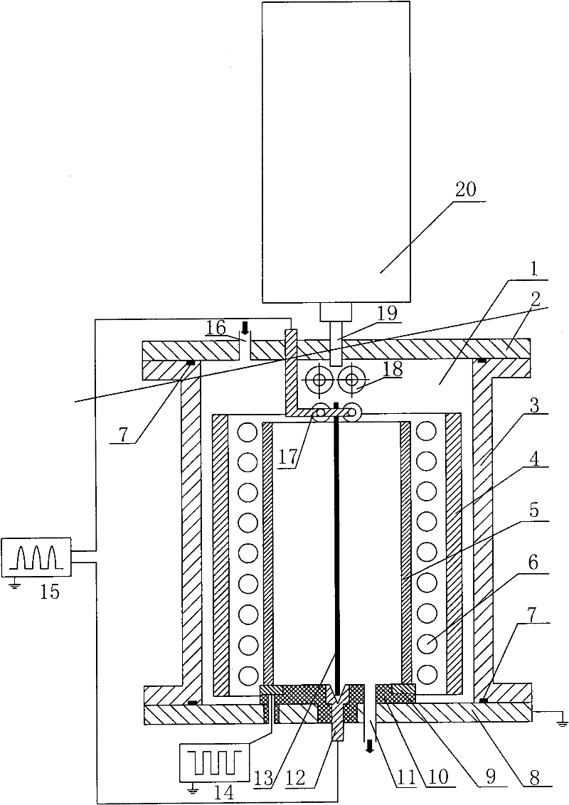
[0023] figure 1 It is a structural schematic diagram of a conductive electric explosion plasma-based low-energy metal ion implantation device of the present invention. As shown in the figure, the disc-shaped upper cover 2 of the device, the cylindrical furnace body 3 and its base 8 form a metal vacuum chamber 1 through a sealing ring 7, and the disc-shaped upper cover 2 is provided with an air inlet 16, and the base 8 There is an air extraction port 11, which is connected with vacuum equipment (such as molecular pump or diffusion pump and mechanical pump unit), and the entire device shell (including the upper cover, furnace body, and base) is grounded; in the metal vacuum chamber 1, the metal pipe fittings 5 ​​ports An electric explosion cathode 17 with a rotating metal runner is arranged at the center; a cylindrical electric explosion anod...


PUM

PropertyMeasurementUnit
lengthaaaaaaaaaa
lengthaaaaaaaaaa

Abstract

The invention relates to a conductor electric exploding plasma-based low-energy metal ion implantation (PBLEMII) device which belongs to the technical field of material surface engineering. In the device, various externally input metal plasma sources are canceled; and the PBLEMII is realized in such a way that an electric exploding cathode and an electric exploding anode are arranged in a metal vacuum chamber; metal or an alloy conductor wire is transmitted between the two electrodes by a wire feeding mechanism, the conductor wire generates electric explosion by rapid pulse discharge to form a metal plasma in an inner cavity of a metal pipe, metal ions are injected into the inner wall of the metal pipe under the action of direct current pulse negative bias of a low-energy ion implantationpower supply, which is applied to the metal pipe, and the injected metal ions are inwards dispersed by combining the synchronous heating function of an auxiliary heating source. The invention has theadvantages of realizing low-energy metal ion implantation into the inner wall of the metal pipe and increasing the depth of a surface modifying layer by the synchronous dispersion of the injected ions and has compact equipment structure and low manufacturing cost.

Description

technical field [0001] The invention relates to a conductive electric explosion plasma-based low-energy metal ion implantation device for surface treatment of the inner wall of a metal pipe fitting, and belongs to the technical field of material surface engineering. Background technique [0002] At present, plasma-based low-energy ion implantation (PBLEII) is a new type of material surface ion implantation technology. In 1995, Lei Mingkai et al. published the article "Plasma source ion nitriding: a new low-temperature, low-pressure nitriding approach" in the Journal of Vacuum Science and Technology A, which reported the plasma-based low-energy ion implantation technology, which has become the current There are typical low-energy ion implantation techniques. Plasma-based low-energy ion implantation technology introduces low-energy ion implantation technology into plasma-based ion implantation. On the one hand, it uses the advantages of low-energy ion beam line implantation t...

Claims


Application Information

Patent Timeline
Patent Type & Authority Patents(China)
IPC IPC(8): C23C14/48
Inventor 雷明凯张锋刚朱小鹏唐毅
Owner DALIAN UNIV OF TECH
Learn More