Internally-cooled solution dehumidifying fresh air handling unit driven by heat pump
A new air unit, solution dehumidification technology, applied in space heating and ventilation, space heating and ventilation details, household heating, etc., can solve the problem of large irreversible losses, reduce working temperature difference, improve indoor air quality, The effect of improving energy efficiency
- Summary
- Abstract
- Description
- Claims
- Application Information
AI Technical Summary
Problems solved by technology
Method used
Image
Examples
Embodiment 1
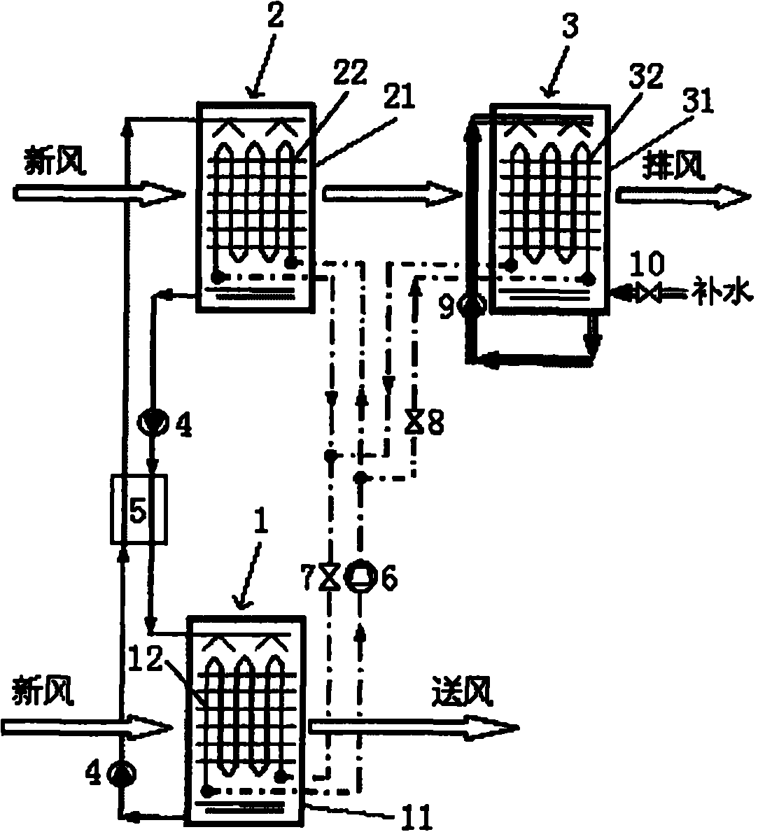
[0018] Such as figure 1 As shown, the fresh air unit of this embodiment includes an internal cooling type dehumidification module 1, an internal heating type regeneration module 2 and an evaporative cooling module 3, and the internal cooling type dehumidification module 1 consists of a dehumidification spray device 11 and a dehumidification heat exchange tube 12, the internal heat regeneration module 2 is composed of a regeneration spray device 21 and a regeneration heat exchange tube 22, and the evaporative cooling module 3 is composed of an evaporative cooling spray device 31 and an evaporative cooling heat exchange tube 32. The internal cooling type dehumidification module 1, the internal heating type regeneration module 2 and the evaporative cooling module 3 form the solution circulation system, the heat pump system and the evaporative cooling water system of the fresh air unit. The internal cooling type dehumidification module 1 is a fresh air channel, the internal heatin...
Embodiment 2
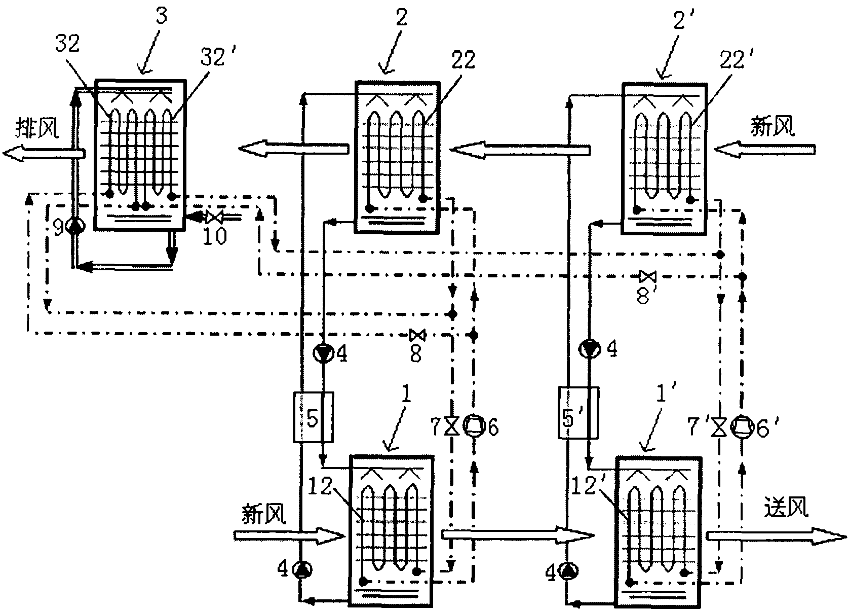
[0025] Such as figure 2 As shown, the difference between this embodiment and Embodiment 1 is that the fresh air unit of this embodiment includes a two-stage solution circulation system and a two-stage heat pump system, that is, two parallel internal cooling dehumidification modules 1, 1', two Internal heat regeneration modules 2, 2' and an evaporative cooling module 3 are connected in parallel, and the evaporative cooling module 3 is provided with two sets of evaporative cooling heat exchange tubes 32, 32'. In this embodiment, the structure of the solution circulation system and the evaporative cooling water system is the same as that of Embodiment 1, and the circulation circuit for exchanging heat with the solution in the heat pump system is also the same as that of Embodiment 1, except that the internal cooling type dehumidification module 1, The dehumidification heat exchange tubes 12, 12' in 1' are respectively connected with two sets of evaporative cooling heat exchange ...
Embodiment 3
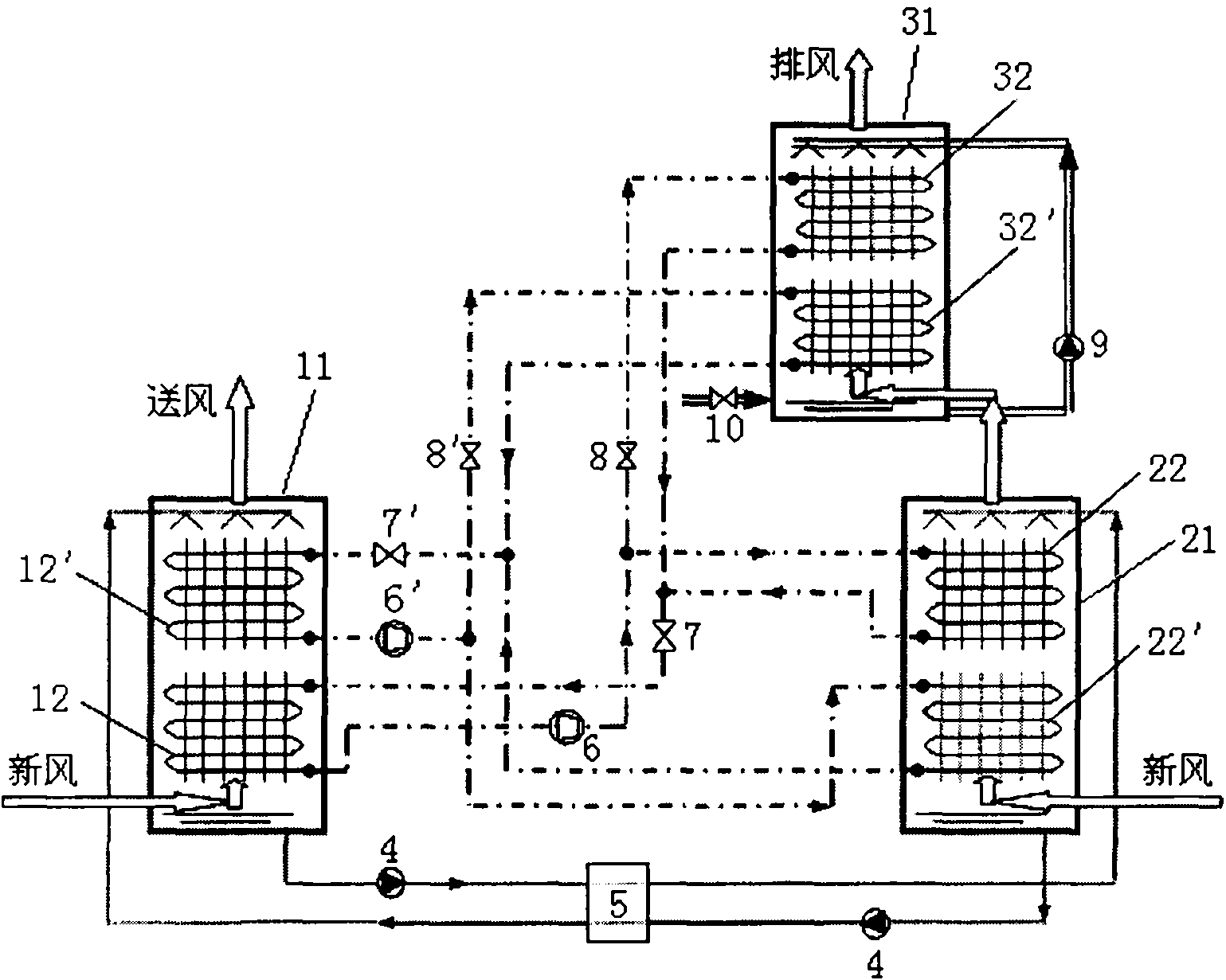
[0029] Such as image 3 As shown, the difference between this embodiment and Embodiment 1 is that the internal cooling type dehumidification module 1, the internal heating type regeneration module 2 and the evaporative cooling module 3 of this embodiment are all provided with two sets of heat exchange tubes, and the internal cooling type dehumidification module Module 1, internal heat regeneration module 2 and evaporative cooling module 3 adopt the form of countercurrent heat exchange. Compressor 6, regenerative heat exchange tube 22, throttle valve 7 and dehumidification heat exchange tube 12 are sequentially connected to form the first and solution heat exchange loop; compressor 6, solenoid valve 8, evaporative cooling heat exchange tube 32, throttle valve 7 and the dehumidification heat exchange pipe 12 are sequentially connected to form the first water heat exchange circulation loop. Compressor 6', regenerative heat exchange tube 22', throttle valve 7' and dehumidificatio...
PUM
 Abstract
Description
Claims
Application Information
 - R&D
- Intellectual Property
- Life Sciences
- Materials
- Tech Scout
- Unparalleled Data Quality
- Higher Quality Content
- 60% Fewer Hallucinations
Browse by: Latest US Patents, China's latest patents, Technical Efficacy Thesaurus, Application Domain, Technology Topic, Popular Technical Reports.
© 2025 PatSnap. All rights reserved.Legal|Privacy policy|Modern Slavery Act Transparency Statement|Sitemap|About US| Contact US: help@patsnap.com


