Small branch line coupler
A branch line and coupler technology, applied in the direction of waveguide devices, circuits, connecting devices, etc., can solve the problem of large integrated circuits occupying an area, meet the needs of bandwidth, and reduce the size of the circuit.
- Summary
- Abstract
- Description
- Claims
- Application Information
AI Technical Summary
Problems solved by technology
Method used
Image

Examples
Embodiment 1
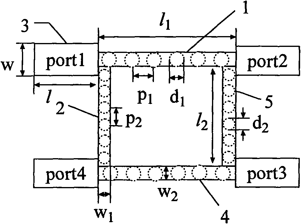
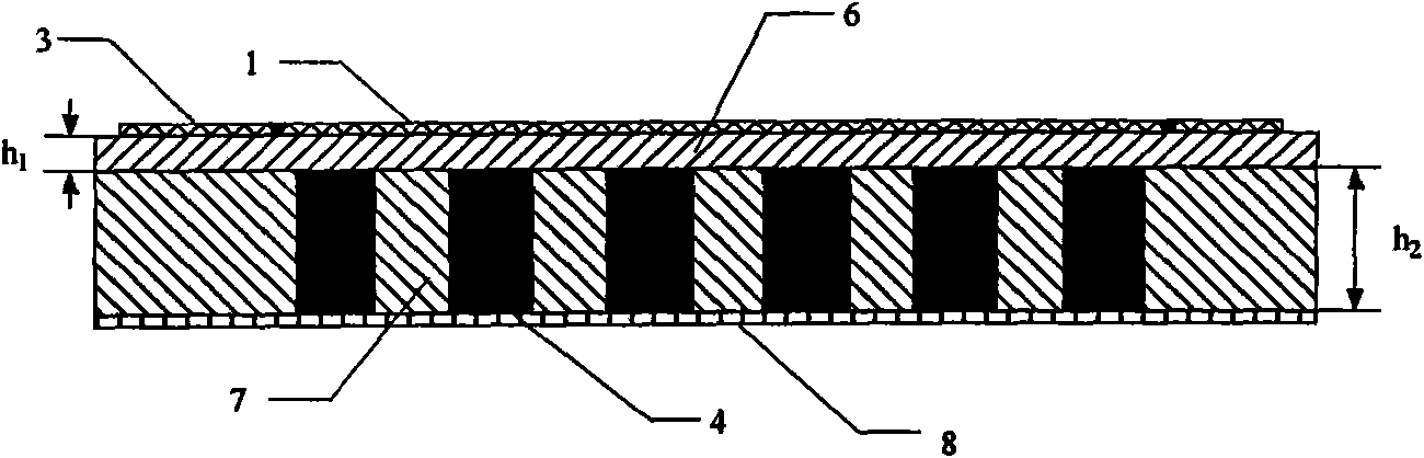
[0016] Embodiment 1: With the help of the very mature microwave integrated circuit processing technology at present, a metal conductive strip is made on the printed circuit board according to the following parameters. The coupler structure is symmetrical up and down, left and right, and the first metal conductive strip is 1 long l 1 20mm, width w 1 =1mm The length of the second metal conduction strip 2 l 2 20.3mm, width w 2 =0.6mm; the length l of the third metal conduction belt 3 is 4mm, and the width w=1.54mm; the diameter d of the metal hole 4 1 =0.9mm, pitch p 1 =1.2mm, the diameter d of the metal hole 5 2 =0.6mm, pitch p 2 = 1mm, their height is h 2 =0.4mm; the heights of media 6 and 7 are h respectively 1 = 0.1 mm, h 2 =0.4mm, the relative permittivity is ε r =2.2; 8 is the grounding plate.
[0017] Table 1
[0018]
[0019] Figure 5 is the HFSS simulation result of the present invention, from Figure 5-1 It can be seen that the branch line coupler is in...
Embodiment 2
[0020] Example 2: The length of the first metal conductive strip 1 is l 1 13.2mm, width w 1 =0.24mm The length of the second metal conduction belt 2 l 2 14mm, width w 2 =0.15mm; the length l of the third metal conduction belt 3 is 2mm, and the width w=1mm; the diameter d of the metal hole 4 1 = 1mm, pitch p 1 =1.1mm, the diameter d of the metal hole 5 2 =0.8mm, pitch p 2 =0.9mm, their height is h 2 =0.45mm; the heights of media 6 and 7 are h respectively 1 =0.05mm, h 2 =0.45mm, the relative permittivity is ε r =4; 8 is the grounding plate. At this time, it can also meet the requirements in the working frequency band (1760MHz-2130MHz).
Embodiment 3
[0021] Example 3: The length of the first metal conductive strip 1 is l 1 34.6mm, width w 1 =3.95mm The length of the second metal conduction belt 2 l 2 35.2mm, width w 2 =2.46mm; the length l of the third metal conduction belt 3 is 4mm, and the width w=2.5mm; the diameter d of the metal hole 4 1 =0.3mm, pitch p 1 =2mm, the diameter d of the metal hole 5 2 =0.2mm, pitch p 2 =1.8mm, their height is h 2 =0.1mm; the heights of media 6 and 7 are h respectively 1 =0.4mm, h 2 =0.1mm, the relative permittivity is ε r =1; 8 is the grounding plate. At this time, it can also meet the requirements in the working frequency band (1760MHz-2130MHz).
PUM
| Property | Measurement | Unit |
|---|---|---|
| Reflection coefficient | aaaaa | aaaaa |
| Isolation | aaaaa | aaaaa |
| Diameter | aaaaa | aaaaa |
Abstract
Description
Claims
Application Information